
Screening apparatus

a screening apparatus and screening technology, applied in the field of screening apparatuses, can solve the problems of unavoidable high speed screening process, 4 times or more of installation area, and 4 times or more of installation area, and achieve the effect of not increasing the price or the installation area of the screening apparatus, and high performan

Inactive Publication Date: 2006-03-30
YOKOGAWA ELECTRIC CORP
View PDF6 Cites 3 Cited by
  • Summary
  • Abstract
  • Description
  • Claims
  • Application Information

AI Technical Summary

Benefits of technology

[0016] An object of the invention is to provide a screening apparatus achieving high speed formation in detecting an image of a well and enabling a high speed processing of, for example, 4 times as much as that of the background art by one set of screening apparatus.
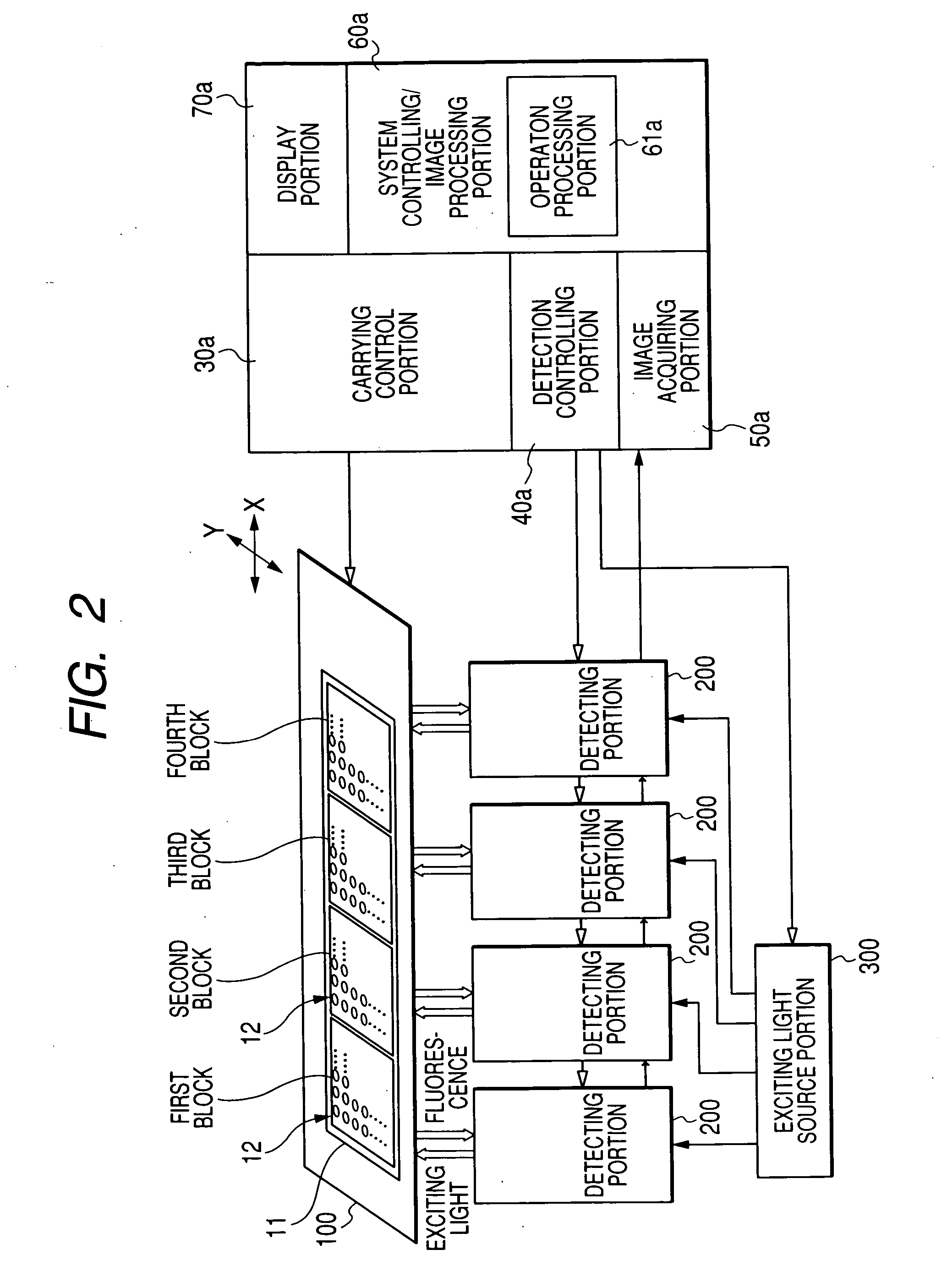
[0018] By operating the plurality of detecting portions in parallel, a measuring amount is increased by an amount of a multiplication of a number of the detecting portions and high speed detection of the image of the well can be achieved. For example, when four detecting portions are provided, four times of the images of the wells can be detected within a time period of measuring by one detecting portion and a measuring speed becomes four times as fast as that in detecting by one detecting portion.
[0025] According to the screening apparatus, the following advantages are achieved.
[0027] Further, as the apparatus, although the number of the detecting portions is increased, price or an installing area thereof is not increased. An advantage of achieving high performance is provided.

Problems solved by technology

However, the following problem is posed in the screening apparatus of the background art.
The competition of developing a new drug is in a direction of being intensified and high speed formation of the screening process is unavoidable.
However, cost becomes 4 times or more, further, 4 times or more of an installing area is needed, which poses a very serious problem.

Method used


Image

  • Screening apparatus
  • Screening apparatus
  • Screening apparatus

Examples


first embodiment

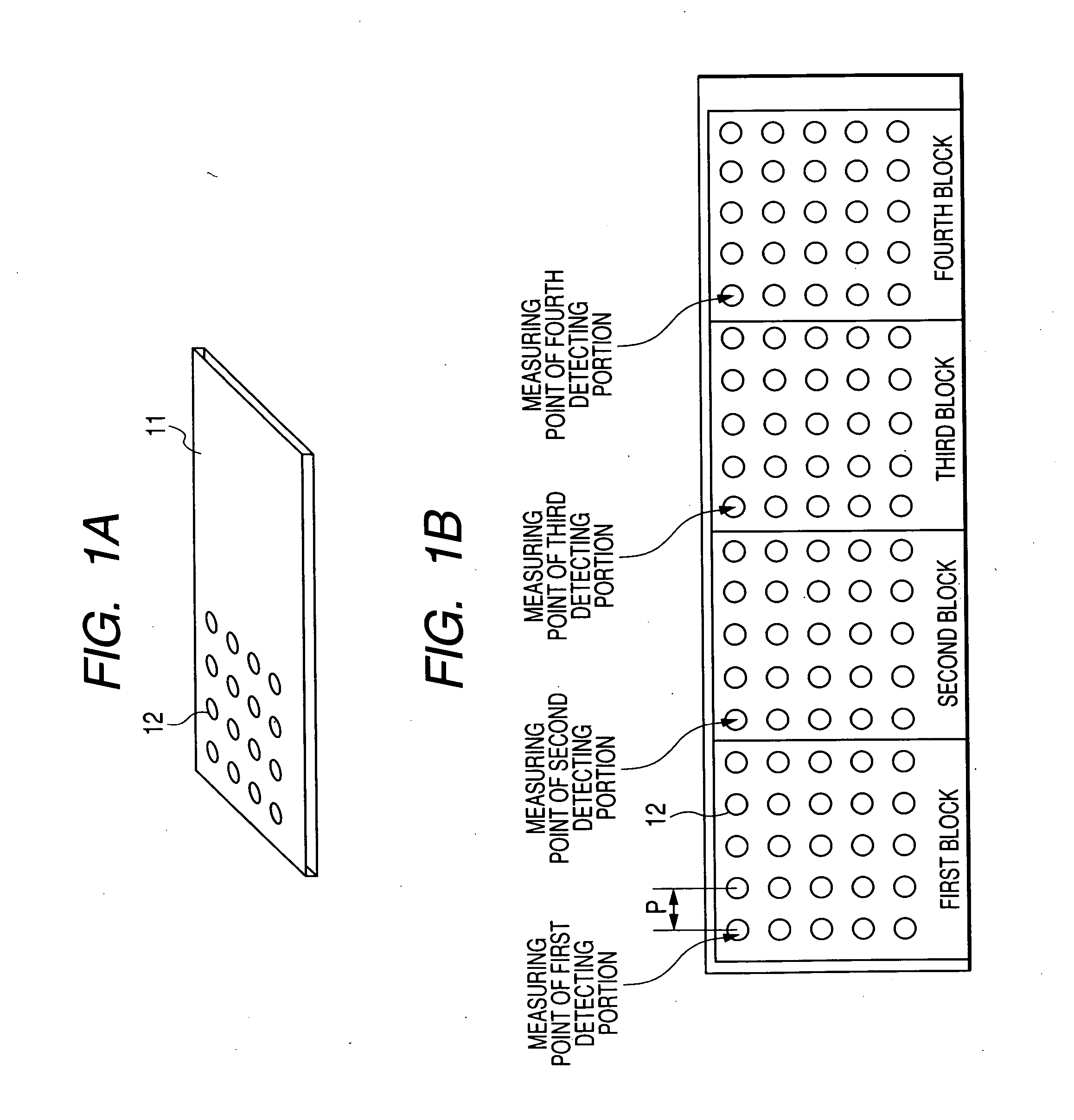
[0037]FIG. 2 is a block diagram showing the screening apparatus of the invention. In FIG. 2, numeral 100 denotes a stage. The stage 100 is formed by a material of transmitting exciting light and fluorescence, is constituted movably in a horizontal direction (XY direction in FIG. 2), and is controlled to be driven by a carrying control portion 30a. The plate 11 is mounted on the stage 100. The plate 11 is formed by a material capable of transmitting exciting light and fluorescence at least at a portion of the well.

[0038] Numeral 200 denotes the detecting portion. The detecting portion 200 detects fluorescence emitted from the plate 11 by applying exciting light to the plate 11. The detecting portion 200 includes the microscope 21 and the detecting optical system 25 shown in FIG. 5. In the embodiment, four detecting portions 200 are provided in the screening apparatus which uses the plate 11 having four blocks.

[0039] The respective detecting portions 200 are fixedly arranged at prede...

second embodiment

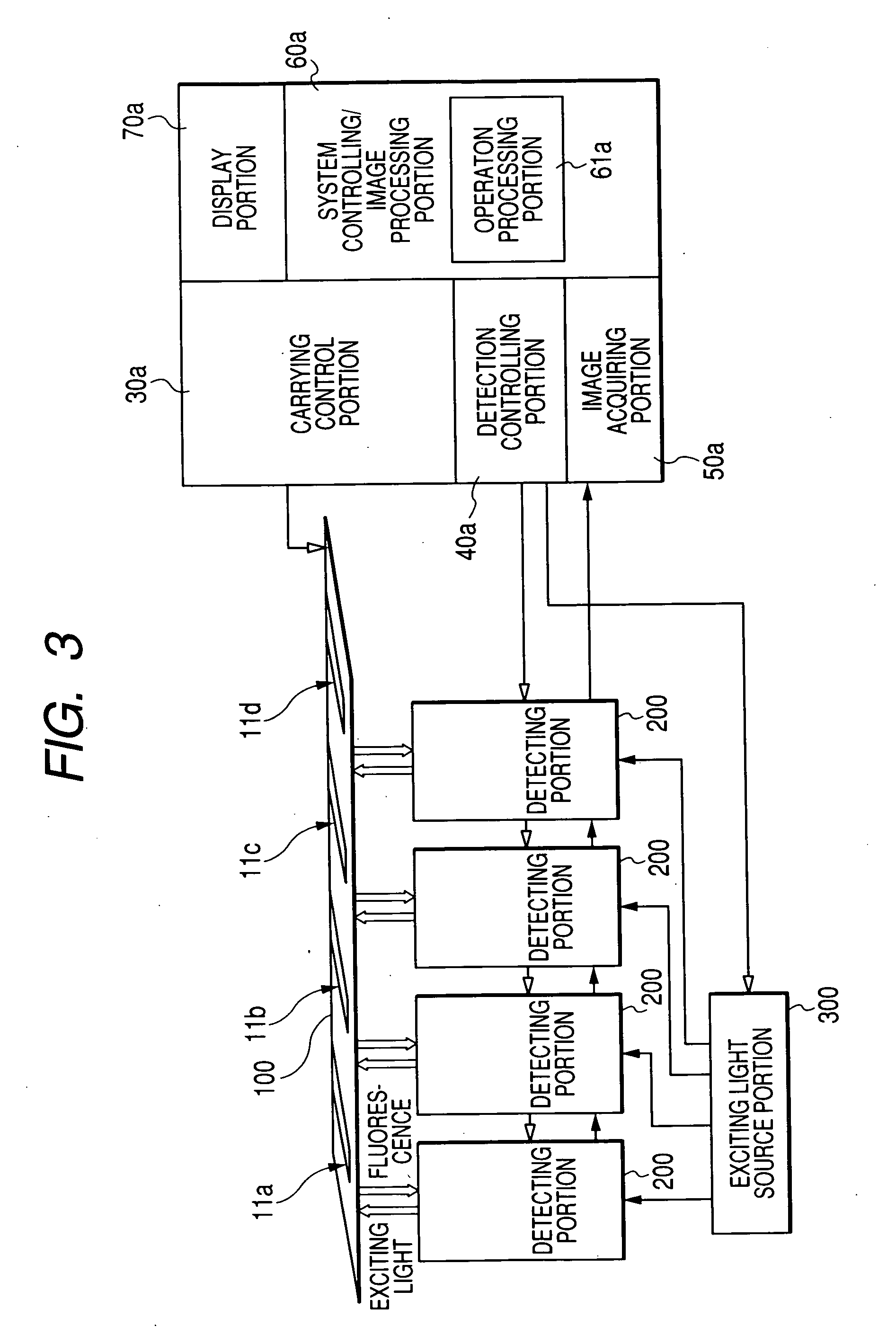
[0053] In the second embodiment, each of the detecting portions 200 measures all of wells of each plate. However, since the four detecting portions 200 are operated in parallel, four plates 11a, 11b, 11c, 11d are measured for the period of the measurement of the plate in the related art. That is, substantial measuring period becomes four times as much as that of the related art.

[0054]FIG. 4 is a block diagram showing the third embodiment of the screening apparatus of the invention. The screening apparatus of the third embodiment is of a rotating stage type. In the third embodiment, four plates are mounted on a rotating stage 100a, which is in a shape of a circular plate, to dispose scatteredly on the same circular ring. The four detecting portions 200 are arranged at four positions on the same circular ring to be opposed to wells of each plate. Further, the rotating stage 100a rotates in a circumferential direction and moves in a radius direction.

third embodiment

[0055] since the rotating stage 100a rotates and moves in XY direction by being controlled by the carrying control portion 30a, wells of each plate can be measured at high speed by the detecting portions 200 fixedly arranged as well as the above embodiments.

[0056] Further, the invention is not limited to the above-described embodiments but further includes numbers of changes and modifications within the range not deviated from the essence.

[0057] For example, a number of the detecting portions 200 may be other than four. However, the number of the detecting portions 200 is same with the number of the divided blocks in FIGS. 1A and 1B and FIG. 2 as well as the number of the plates in FIG. 3 and FIG. 4.

[0058] Further, the detecting optical system 25 of the detecting portion 200 may be a cofocal scanner of a Nipkow system. An example of the cofocal scanner of a Nipkow system is described in JP-A-5-60980.

[0059] Further, the screening apparatuses can be utilized not only for the scree...


PUM


Abstract

A screening apparatus detects images of a plurality of wells provided at a plate to perform screening in a new drug process. The screening apparatus has a plurality of detecting portions which are fixedly arranged and individually detect images of wells different from each other, a movable stage on which the plate is mounted, a carrying portion which moves the stage so that positions of the wells of the plate correspond with measuring positions of the detecting portions, and a detection controlling portion which controls the detecting portions to simultaneously detect the images of the wells different from each other.

Description

CROSS-REFERENCE TO RELATED APPLICATIONS [0001] This application is based upon and claims the benefit of priority from the prior Japanese Patent Applications No. 2004-286373, filed on Sep. 30, 2004, the entire contents of which are incorporated herein by reference. BACKGROUND OF THE INVENTION [0002] 1. Field of the Invention [0003] The present invention relates to a screening apparatus used in a drug discovery process, which enables to perform a screening process at high speed. [0004] The present invention can be utilized not only for screening but for a target search in the same drug discovery process. [0005] 2. Description of the Related Art [0006] JP-T-1-2002-525603 is referred to as a related art of a screening apparatus in a drug discovery process. [0007]FIG. 5 is a block diagram showing an example of a screening apparatus based on a screening system shown in JP-T-1-2002-525603. There is used a high contents screening (HCS) apparatus for putting a compound group which is a candi...

Claims


Application Information

Patent Timeline
IPC IPC(8): G06K9/00C12M1/34
CPCG01N21/6428G01N2035/00158G01N21/6458G01N21/6452
Inventor ANYOJI, AKIHIKOHORI, KATSUYOSHIMIKURIYA, KENTA
Owner YOKOGAWA ELECTRIC CORP
Learn More