Polymer derived ceramic materials

a technology of ceramic materials and polymer derived materials, applied in the field of ceramic materials, can solve the problems of difficult control in small scale structures, unsuitable high temperature materials formed by this process, and difficult to meet the needs of many applications, and achieve high polymerization speed, delay the effect of gelation and high double bond conversion

Inactive Publication Date: 2006-03-30
UNIV OF COLORADO THE REGENTS OF
View PDF7 Cites 88 Cited by
  • Summary
  • Abstract
  • Description
  • Claims
  • Application Information

AI Technical Summary

Benefits of technology

[0008] The invention provides methods of rapidly fabricating polymer derived ceramic materials (e.g., with controlled shapes and structures) and related compositions. The reaction schemes described herein are largely based upon a thiol-ene photopolymerization mechanism. Thiol-ene photopolymerizations provide various advantages including high polymerization speeds in the presence of little or no photoinitiator, the ability to delay gelation, and the ability to achieve high double bond conversions. The addition of thiols to polymerizable vinyl containing ceramic precursors further permits the formation of structures that are

Problems solved by technology

Polymers, silicon, and glass are commonly used materials for making, e.g., MEMS/NEMS, though many of these materials are not suitable for high temperatures (e.g., in excess of 1000° C.) or other harsh environmental applications.
However, the additives used in these materials for densification tend to reduce the mechanical properties of the resulting ceramic structures, rendering materials formed by this process unsuitable for many applications.
Further, the dimensional tolerances of the

Method used


Image

  • Polymer derived ceramic materials
  • Polymer derived ceramic materials
  • Polymer derived ceramic materials

Examples


example i

[0048] Experimental

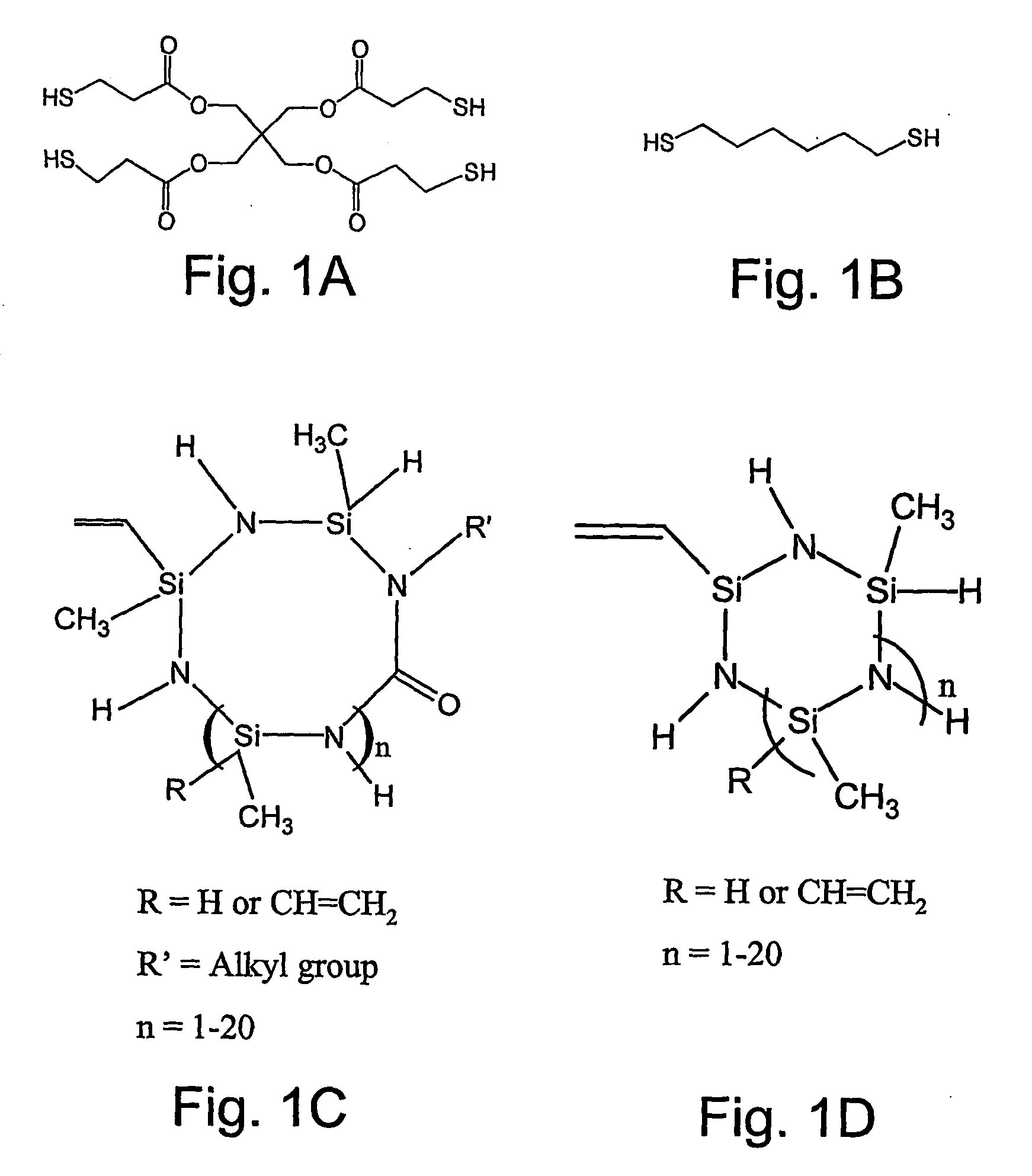
[0049] The monomers utilized in this example were pentaerythiritol tetra(3-mercaptopropionate) (tetrathiol) (donated), 1,6-hexanedithiol (dithiol) (Aldrich, Milwaukee, Wis.), and vinyl containing ceramic precursor monomers, VL20 and CERASET (Kion Corporation, New York, N.Y.). The photoinitiator utilized was 2,2-dimethoxy-2-phenyl acetophenone (DMPA) (Ciba-Geigy, Hawthorne, N.Y.). All monomers and the photoinitiator were used as received, and the structures of the monomers used are shown in FIGS. 1A-D.

[0050] FTIR studies were conducted using a Nicolet 750 Magna FTIR spectrometer with a KBr beamsplitter and an MCT / A detector. Series scans were recorded, taking spectra at the rate of approximately 5 scans per second while the FTIR sample chamber was continuously purged with dry air. Samples were irradiated until the reaction was complete, as indicated by the double bond and thiol peak absorptions remaining constant. Thiol functional group conversion was monitored u...

example ii

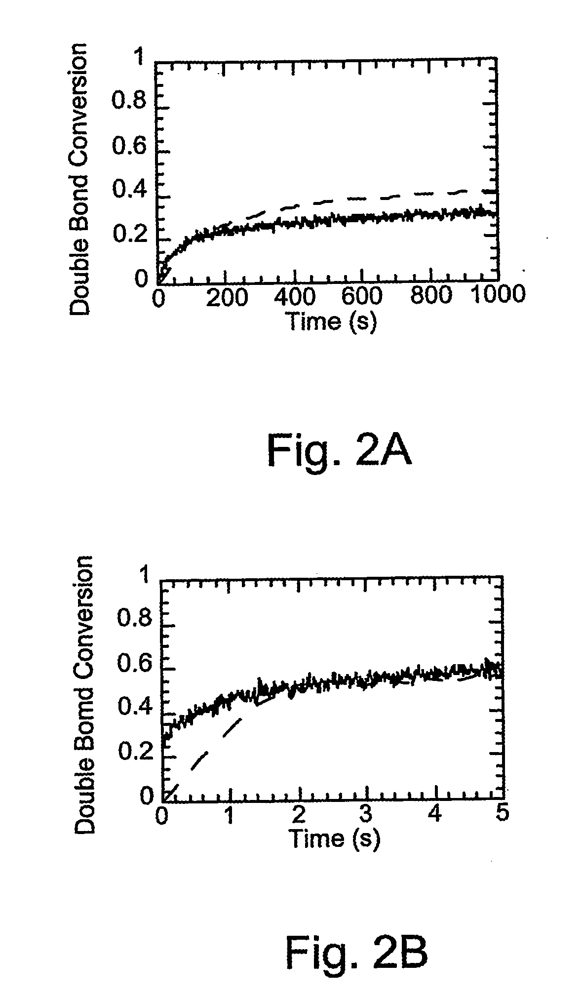
[0063] Pentaerythritol tetra(3-mercaptopropionate) and (a KiON™ VL20 polysilazane) were copolymerized, under identical conditions (other than having far less initiator) to those of a non-thiol containing system that comprised only the polysilazane. The results showing cure times and overall conversions for bulk polysilazane (VL20 polysilazane) and a thiol / polysilazane mixture (thiol / VL20 polysilazane) consisting of 1:5 weight fraction of thiol to polysilazane monomers are presented in Table III. The samples were irradiated at 57 mW / cm2 using 6 wt % DMPA as the photoinitiator for VL20 bulk polymerization and 0.02 wt % for the thiol-VL20 polymerization. Note that the thiol-ene photopolymerization achieved the same conversion in 1-2 seconds as the traditional photopolymerization achieved in approximately 500 seconds despite the presence of 300 times more initiator in the traditional system.

TABLE IIICurePercent Double BondPolymerizationTime (seconds)ConversionBulk KiON ™ VL2060040Poly...

example iii

[0064] Thiol-ene photopolymerizations also lead to enhanced capabilities in photolithographic processes including low shrinkage and greater resolution. This is depicted in FIGS. 6A-E, which show images of a photolithographic mask, polymer, and pyrolized ceramic. More specifically, FIG. 6A shows a polymer 2-D channel of 800 μm made from 1:5 (wt ratio) of tetrathiol:VL20. FIG. 6B shows a pyrolyzed sample made from the pyrolysis of the device shown in FIG. 6A. FIGS. 6 C and D show a top view and a side view, respectively, of an 800 μm polymer 3-D channel filled with red dye. FIG. 6E shows the sample from FIGS. 6 C and D after pyrolysis with the 3-D channel. Decreased quantities of initiator molecules allow for formation and patterning of much thicker samples than can typically be achieved with traditional polymerization systems. Thiol-ene polymerizations can, in fact, be conducted without any added photoinitiator molecules (Cramer et al. (2002) Macromolecules 35:5361). Inherent in a st...


PUM

PropertyMeasurementUnit
Temperatureaaaaaaaaaa
Molar densityaaaaaaaaaa

Abstract

The invention provides a composition that includes a first monomer comprising at least one ethylenically unsaturated group and at least one Si—N linkage, and a second monomer comprising at least one thiol functional group. The invention also provides a method of forming a ceramic material and process for forming a three-dimensional ceramic material.

Description

COPYRIGHT NOTIFICATION [0001] Pursuant to 37 C.F.R. § 1.71(e), Applicants note that a portion of this disclosure contains material which is subject to copyright protection. The copyright owner has no objection to the facsimile reproduction by anyone of the patent document or patent disclosure, as it appears in the Patent and Trademark Office patent file or records, but otherwise reserves all copyright rights whatsoever. CROSS-REFERENCES TO RELATED APPLICATIONS [0002] This application claims the benefit of U.S. Provisional Application No. 60 / 405,046, filed Aug. 20, 2002, the disclosure of which is incorporated by reference. FIELD OF THE INVENTION [0003] The present invention relates generally to ceramic materials and to methods of forming these materials. BACKGROUND OF THE INVENTION [0004] The photopolymerization or radiation-based curing of light sensitive materials is a multibillion dollar business. The photopolymer products of these processes are typically derived from polymers, o...

Claims


Application Information

Patent Timeline
IPC IPC(8): C08F2/46B05D3/06B29C35/08C04BC04B35/14C04B35/565C04B35/584C08F230/08C08F283/12C08F290/06C08G75/04C08G77/00C08J3/28G03F7/00G03F7/075
CPCC04B35/584C04B2235/48C08F2/46C08F230/08G03F7/0755C08F290/068C08G75/045G03F7/0037C08F283/12B29C35/08C04B35/14C04B35/565C08G77/00
Inventor BOWMAN, CHRISTOPHER N.CRAMER, NEILREDDY, SIRISH
Owner UNIV OF COLORADO THE REGENTS OF
Why Eureka
Try Eureka