Method to extend the utilization of a catalyst in a multistage reactor system

Inactive Publication Date: 2006-04-06
EI DU PONT DE NEMOURS & CO
View PDF18 Cites 19 Cited by
  • Summary
  • Abstract
  • Description
  • Claims
  • Application Information

AI Technical Summary

Benefits of technology

[0012] In one embodiment of the invention, the temperature may be optionally increased after step (a) to continuously meet the specification for the product as it leaves the most downstream reactor. Subsequently,

Problems solved by technology
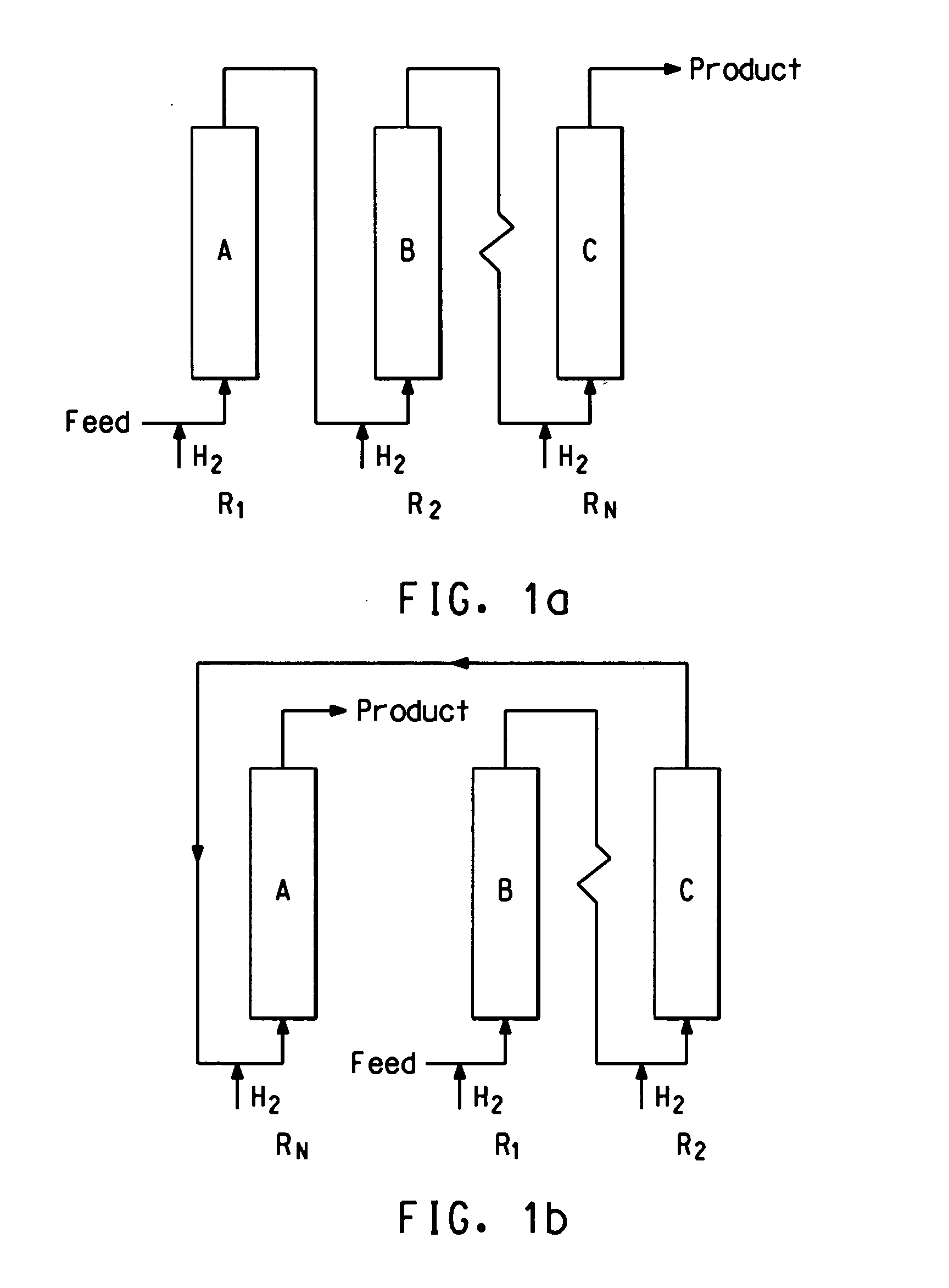
At low to moderate temperatures (lower than about 200° C.) of hydrogenation, metal sulfides do not have practical hydrogenation activity and thus are considered the poisoned form of the metallic catalysts.
In a single reactor, the poisoned zone will progress downstream, gradually diminishing the activity of the upstream portion of the catalyst bed to the point where the reactor cannot produce a product with desired specifications.
Although the entire reactor bed cannot meet the required specification, the catalyst downstream from the poisoned zone still is relatively active and may only be slightly deacti

Method used


Image

  • Method to extend the utilization of a catalyst in a multistage reactor system
  • Method to extend the utilization of a catalyst in a multistage reactor system
  • Method to extend the utilization of a catalyst in a multistage reactor system

Examples


example 1

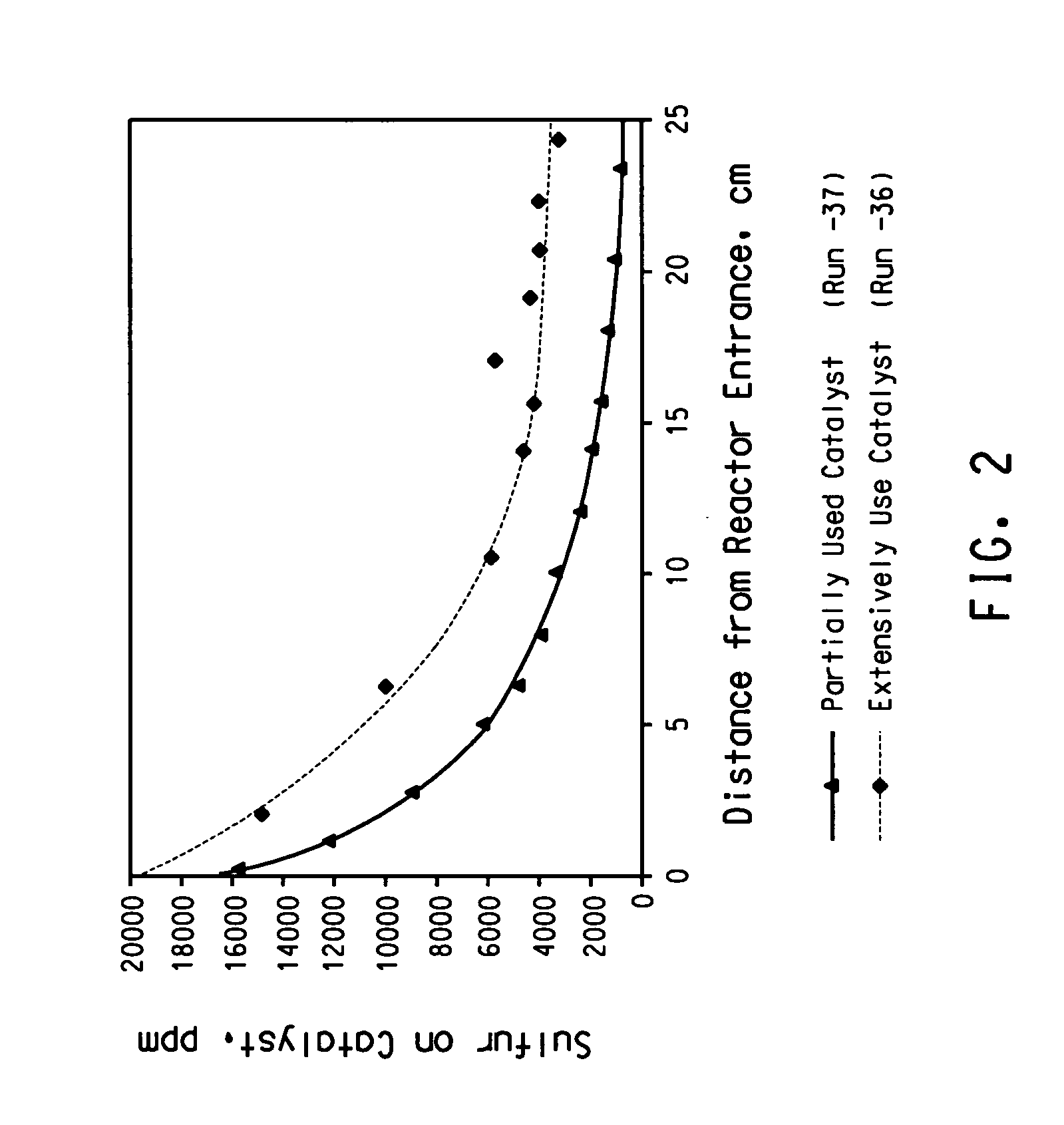
[0053] Run-36 was conducted in a single reactor with 250 mm catalyst packing at various temperatures (80° C., 100° C., and 120° C., but mostly at 100° C.) at 2860 kPa, 0.8 1 / h LHSV with H2 to PDO flow ratio of 6.1 scc / g. The feed had 16 ppm sulfur and the run continued until the catalyst was significantly deactivated. At the end of the run, the catalyst was taken out in segments and analyzed for its sulfur content.

[0054]FIG. 2 shows the sulfur profile in the reactor, indicating that sulfur deposition is predominantly near the reactor entrance.

[0055] Furthermore, this test showed that the desulfurization rate is much faster than the hydrogenation rate to remove color. The following Table 1 shows that at various conditions of operation while the percentage reduction in UV-270 nm varies from 65 to 94%, the sulfur concentration in the PDO exiting the reactor is below the detection limit of 1 ppm.

TABLE 1TemperatureLHSV% Reduction% Reduction° C.1 / hUV-270Sulfur800.865.3approx. 1001000....

example 2

[0056] Run-37 was conducted in a single reactor with 250 mm catalyst packing at various temperatures (80° C., 100° C., and 120° C., but mostly at 100° C.) at 2860 kPa, 0.8 1 / h LHSV with H2 / PDO=6.1 scc / g. The run continued until the reactor bed was partially deactivated but was still able to meet the desired UV specifications. The run was stopped and the catalyst was removed in segments and analyzed for sulfur.

[0057]FIG. 2 shows more distinctly that sulfur deposits predominantly near the entrance of the bed. The partially used bed (Run-37) shows most of the sulfur accumulated in the front one third of the bed. The extensively used catalyst bed (Run-36) shows most of the sulfur accumulated in the first half of the bed.

example 3

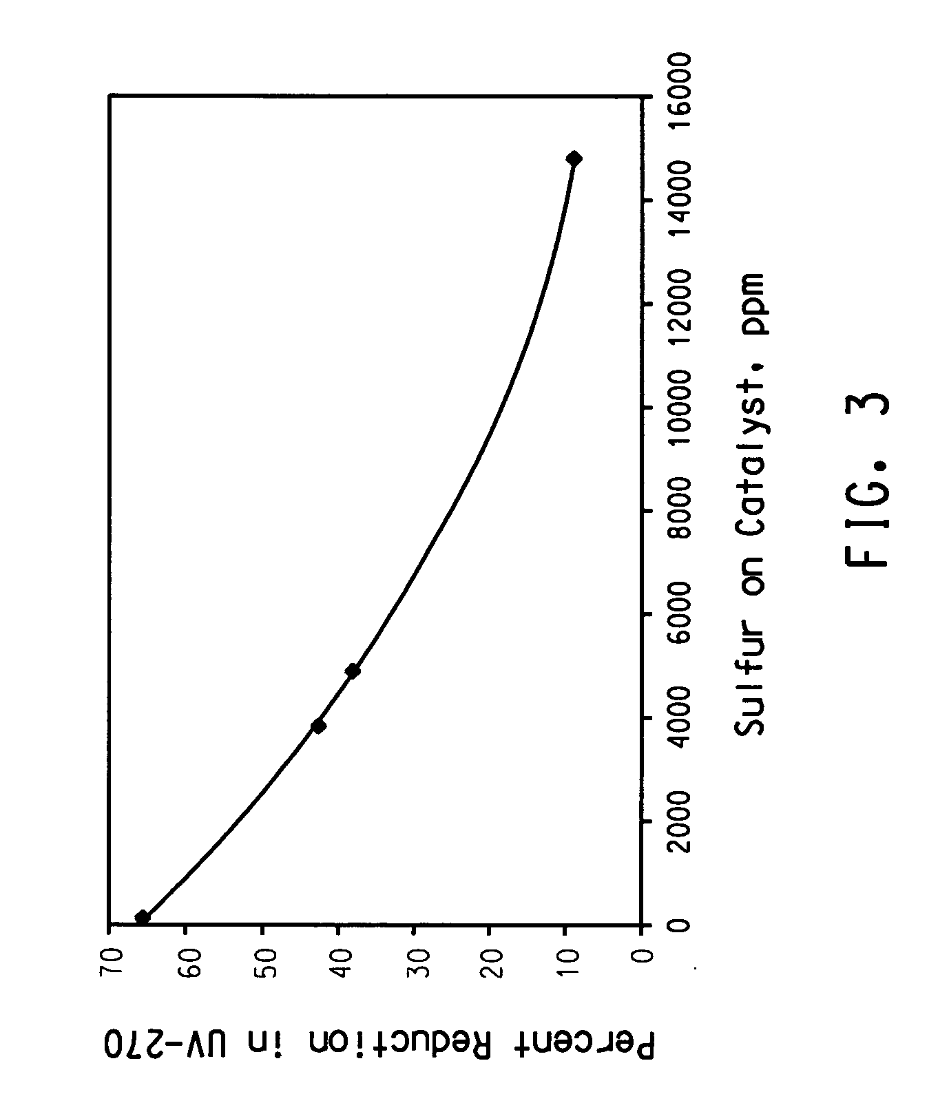
[0058] Three segments of the spent catalyst from Run-36 were sampled to represent poisoned catalysts with different levels of sulfur on the catalyst. The hydrogenation activities of these samples and that of a sample of the fresh catalyst were measured under identical conditions of 3.8 1 / h LHSV, 100° C., and 2860 kPa.

[0059]FIG. 3 shows that the catalyst activity for color removal, as measured by percent reduction in the absorption at UV-270 nm, decreases with increasing level of sulfur accumulated on the catalyst.


PUM

PropertyMeasurementUnit
Temperatureaaaaaaaaaa

Abstract

The invention provides a method to extend the utilization of a catalyst in a multistage reaction system, provided that a primary reaction and a secondary (or more) catalyst-poisoning reaction occur on the same catalyst, and the rate of the secondary (or more), catalyst-poisoning reaction is faster than the rate of the primary reaction.

Description

CROSS REFERENCE TO RELATED APPLICATION [0001] This application claims the benefit of U.S. Provisional Application No. 60 / 615,083, filed Oct. 1, 2004, which is hereby incorporated by reference.FIELD OF THE INVENTION [0002] This invention relates to a method to extend utilization of a catalyst in a multistage reactor system. More specifically, the invention relates to a method to extend catalyst utilization in sets of reactions catalyzed on the same catalyst (i.e., hydrogenation and desulfurization), where one reaction causes catalyst poisoning. BACKGROUND [0003] Hydrogenation is a commonly practiced process in petroleum, chemical, and food industries. Depending on the feedstocks and the severity of the operating conditions (e.g., temperature, pressure, and contact time), the hydrogenation process may saturate unsaturated bonds, reduce aldehydes and ketones, reduce carboxylic acids and their esters, reduce nitrogen-containing compounds, reduce sulfur-containing compounds, and cause nu...

Claims


Application Information

Patent Timeline
IPC IPC(8): C10G65/02C10G65/04
CPCB01J8/0085B01J8/0457B01J35/0006B01J2208/00707B01J2219/0004C10G65/02B01J8/04B01J8/00C10G65/04
Inventor SEAPAN, MAYISDIFFENDALL, GEORGE F.
Owner EI DU PONT DE NEMOURS & CO
Why Eureka
Try Eureka