Liquid filter

Inactive Publication Date: 2006-04-06
MANN HUMMEL GMBH
View PDF4 Cites 53 Cited by
  • Summary
  • Abstract
  • Description
  • Claims
  • Application Information

AI Technical Summary

Benefits of technology

[0032] In a vacuum system, i.e., a system with a liquid filter which is situated in the path of flow upstream from the fuel pump, redundant protection against leakage through the discharge valve is achieved by providing both an electromagnetic delivery pump and an electromagnetic discharge valve situated downstream in the direction of flow. In the event of pump failure due to a short circuit and/or mechanical failure, the discharge valve nevertheless remains tightly sealed and thus prevents water and fuel from escaping.
[0033] In accordance with one advantageous embodiment of this method, the water discharge is preferably turned off after a predetermined period of time has elapsed. Due to the characteristic quantities of the water discharge such as the volume flow rate and the water volume in the water collecting area up to the maximum water level, it is easy to specify a period of time within which the water present in the water collecting area will be completely discharged. If the volume flow of the water to be discharged deviates from expectations, then through a corresponding signal of the minimum water level sensor to the

Problems solved by technology

Since the water contained in the fuel may cause damage due to oxidation of the metal parts with which it comes in contact, it is well known that the water content of fuel must be filtered out in the fuel filter, especially in the case of diesel fuel filters.
One disadvantage of the arrangement described above is that due to the combination of parts which are movable relative to each other, the

Method used


Image

  • Liquid filter
  • Liquid filter
  • Liquid filter

Examples


Embodiment Construction

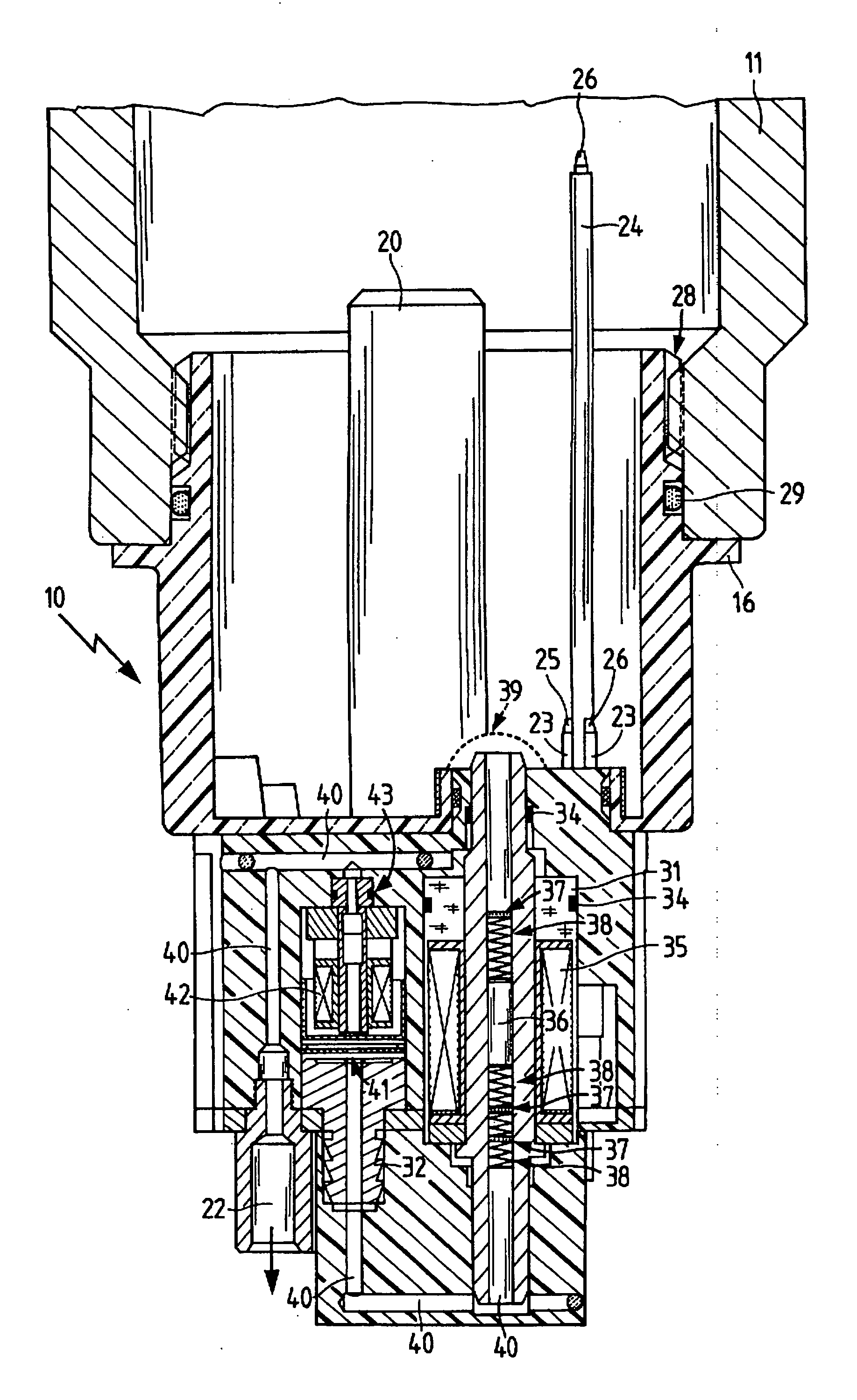
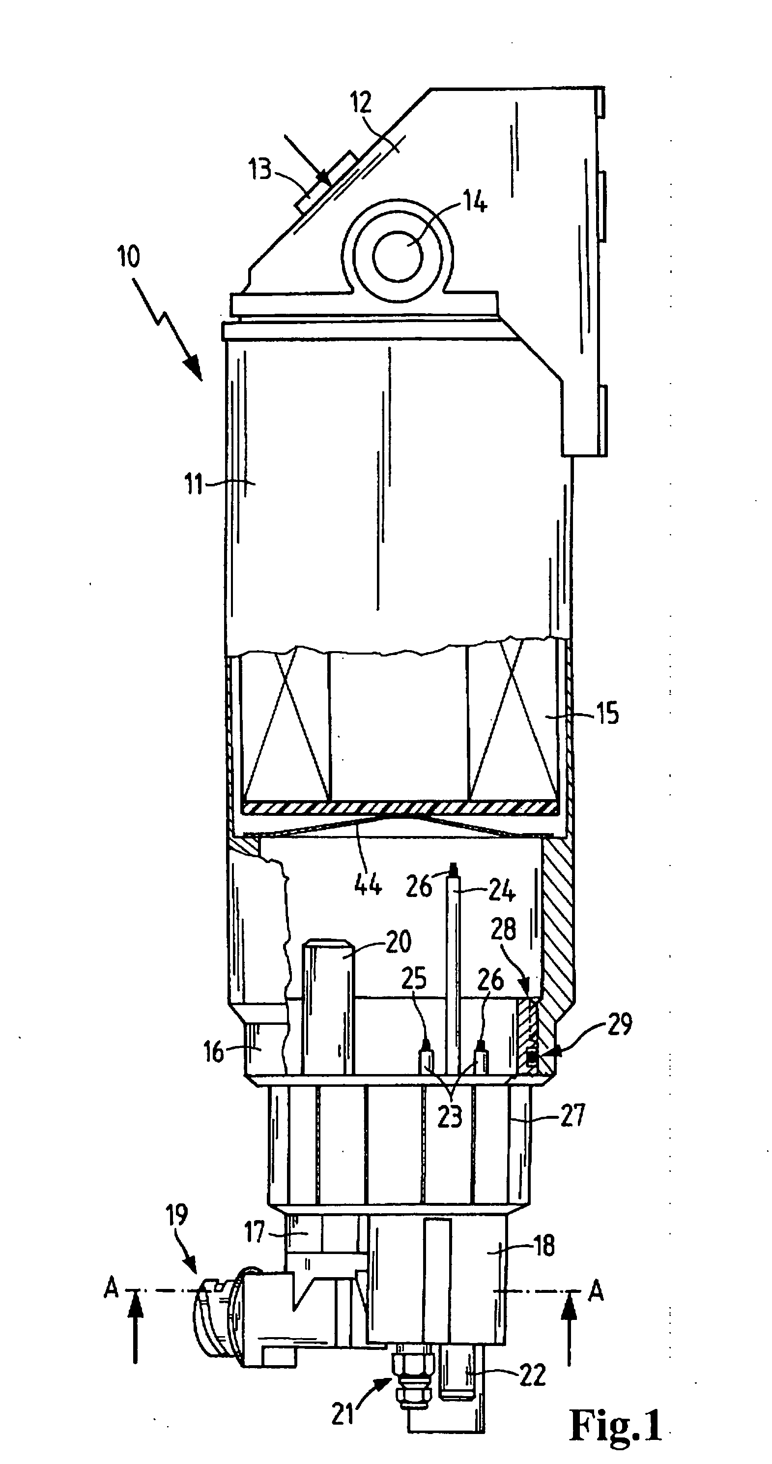
[0040]FIG. 1 is a partial sectional view of a liquid filter 10. The liquid filter 10 has a housing 11 with a housing head 12 and an inlet 13 and an outlet 14. A filter element 15 is arranged in a sealed manner between the inlet 13 and the outlet 14, supported by a cartridge guide 44 in the housing 11. Beneath the housing 11, a collecting tank 16 is arranged. Below the collecting tank 16 in turn there is a heater tank 17 and a water discharge device 18.

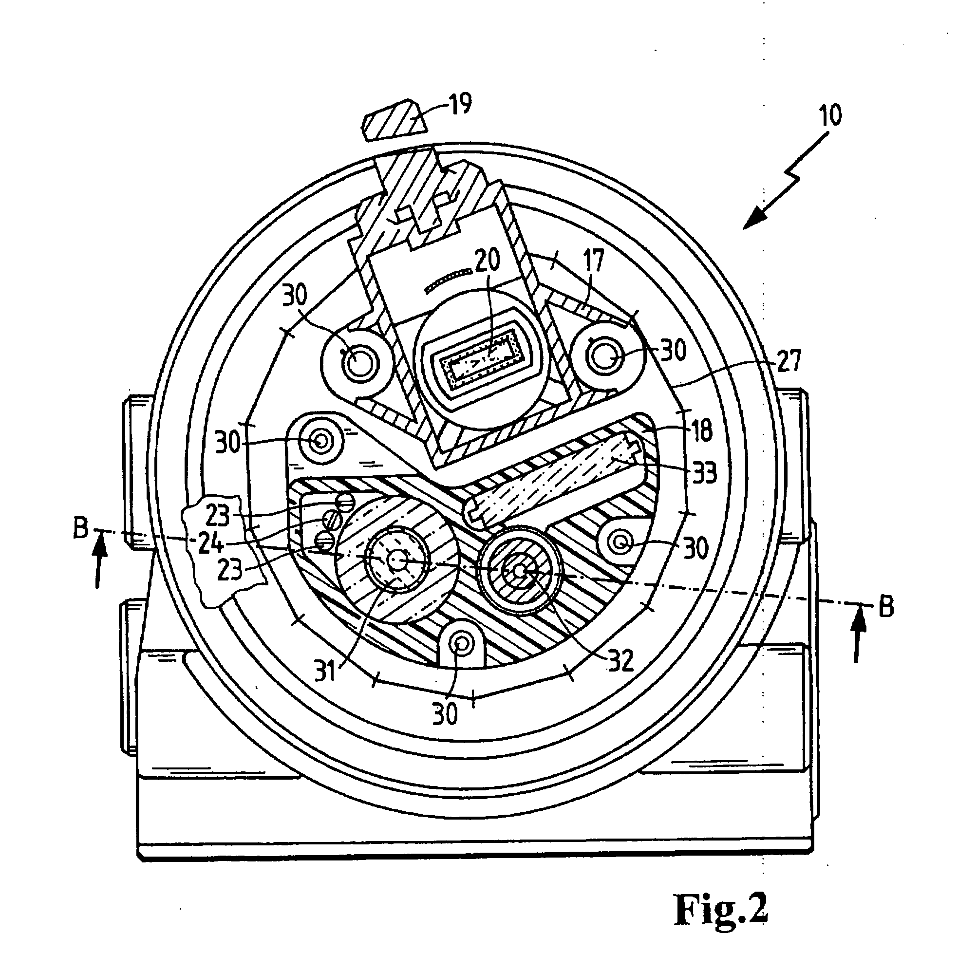
[0041] The heater tank 17 has a connecting plug 19 for connection to an electric power source and a PTC heater 20 which extends into the collecting tank 16. The heater tank 17 and the collecting tank 16 are connected to one another in a sealed manner. The water discharge device 18 has a cable feed 21, likewise for supplying electric power and for supplying signals from a control unit (not shown), and a water outlet 22. The water outlet 22 can be connected to other elements which are used to treat the discharged water, e.g., via a hose...


PUM

PropertyMeasurementUnit
Temperatureaaaaaaaaaa
Timeaaaaaaaaaa
Pressureaaaaaaaaaa

Abstract

A liquid filter, particularly for filtering diesel fuel, having a device for automatically discharging water separated from the fuel in the liquid filter, including a housing with an inlet and an outlet for the liquid to be filtered, a filter element arranged in a sealed manner between the inlet and the outlet, and a water collecting area underneath the filter element, in which the automatic water discharge device is connected in a sealed manner to the housing below the water collecting area, and includes in a single housing a sensor for sensing the water level in the water collecting area, an electrically operated water discharge device for discharging water from the water collecting area, a water outlet, and a microprocessor operatively connected to the sensor, to the water discharge device and to a control unit of the internal combustion engine, such that in a predetermined operational state of the internal combustion engine while the engine is running, the microprocessor activates the water discharge device when the sensor emits an appropriate signal indicating water in the collecting area.

Description

BACKGROUND OF THE INVENTION [0001] The present invention relates to a liquid filter having an automatic water discharge and to a method for automatically discharging water from such a liquid filter. [0002] The fuel for internal combustion engines is normally filtered before being used for operation of the internal combustion engine. Since the water contained in the fuel may cause damage due to oxidation of the metal parts with which it comes in contact, it is well known that the water content of fuel must be filtered out in the fuel filter, especially in the case of diesel fuel filters. Due to the greater specific gravity of water, the water then collects in a water collecting tank in a lower area of the fuel filter. As soon as the water level in the filter has reached a certain height, the water must be removed from the filter to prevent the filter from malfunctioning. [0003] U.S. Pat. No. 6,783,665 (=WO 01 / 33069) discloses a fuel filter with a water collecting chamber situated ben...

Claims


Application Information

Patent Timeline
IPC IPC(8): B01D17/02
CPCB01D35/26B01D36/005B01D36/006F02M25/0222F02M37/221Y02T10/121B01D36/008F02M37/28F02M37/30Y02T10/12
Inventor HERRMANN, RALFFISCHER, HELMUTH
Owner MANN HUMMEL GMBH
Why Eureka
Try Eureka