Apparatus of antenna with heat slug and its fabricating process
- Summary
- Abstract
- Description
- Claims
- Application Information
AI Technical Summary
Benefits of technology
Problems solved by technology
Method used
Image
Examples
first embodiment
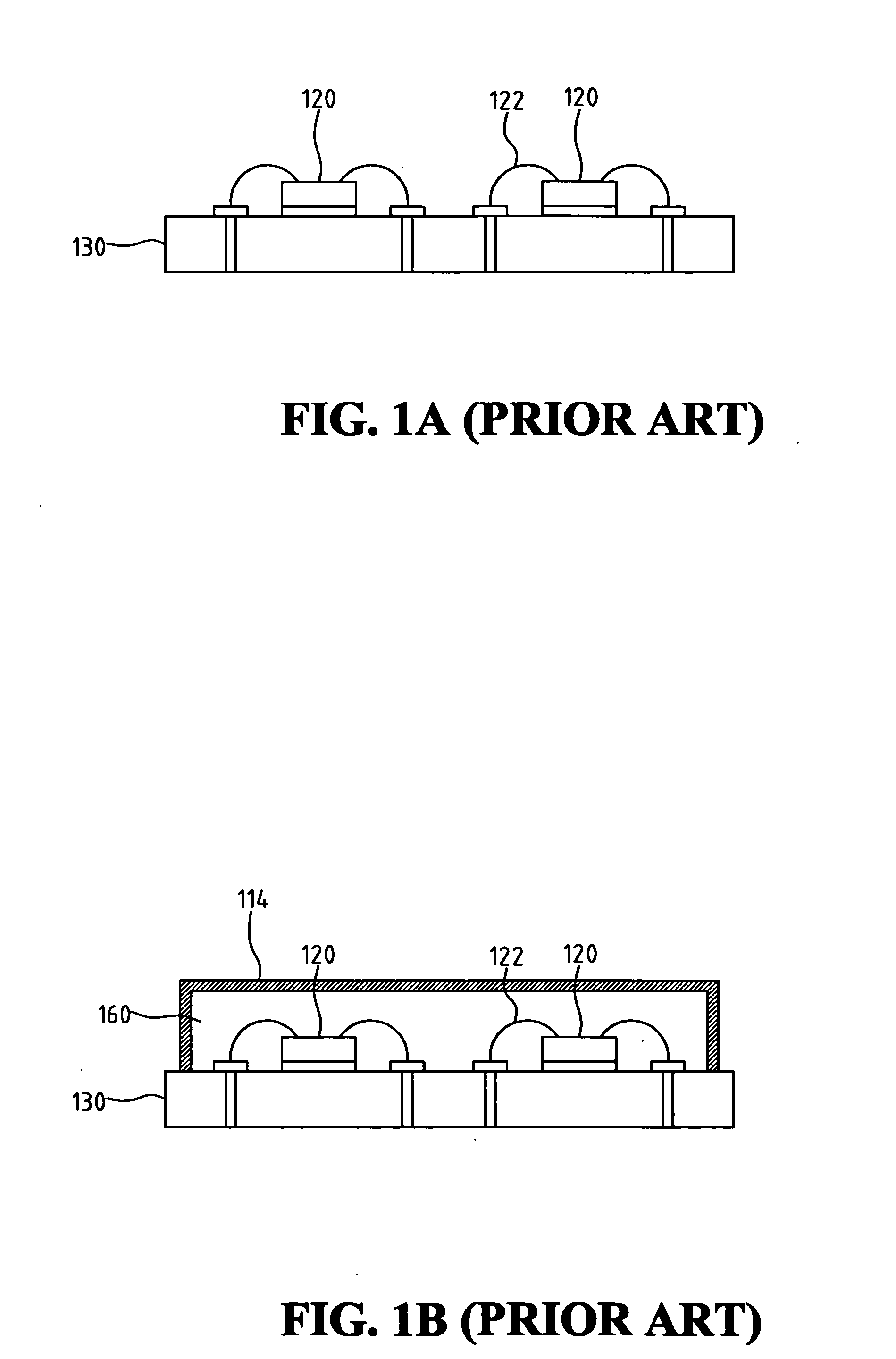
[0043]FIG. 3A shows a perspective view of the present invention. In this embodiment, the antenna with heat slug includes an antenna 311, an antenna feed metal sheet 312, at least a connection metal sheet 313, a heat slug 314, at least a chip 320, an antenna signal transmission line 321, a plurality of metal belts 340, a mold compound (described and shown in FIG. 3B) and a substrate 330. Antenna 311, antenna feed metal sheet 312, at least a connection metal sheet 313, heat slug 314 and support elements 315 constitute an antenna with heat slug module 310, which has a single metal sheet structure.
[0044] Substrate 330 has an upper surface 331 and a lower surface 332. Antenna signal transmission line 321 and a plurality of metal belts are formed on upper surface 331, where a chip 320 is attached. Chip 320 is connected to antenna signal transmission line 321 and bump pad 341 through metal wire 322. One end of connect metal sheet 313 is connected to antenna 311, and the other end is connec...
second embodiment
[0058]FIGS. 6A-6E show the fabricating process of the second embodiment according to the present invention.
[0059] The second embodiment has a fabricating process similar to that of the first embodiment. The difference is that the single metal sheet is cut or molded into a different shape in the process. First, as shown in FIG. 6A, at least a chip 520 is attached to upper surface 531 of substrate 530, on which antenna signal transmission line 521 and a plurality of metal belts 540 are already formed. Wire bond 522 is then formed to connect chip 320.
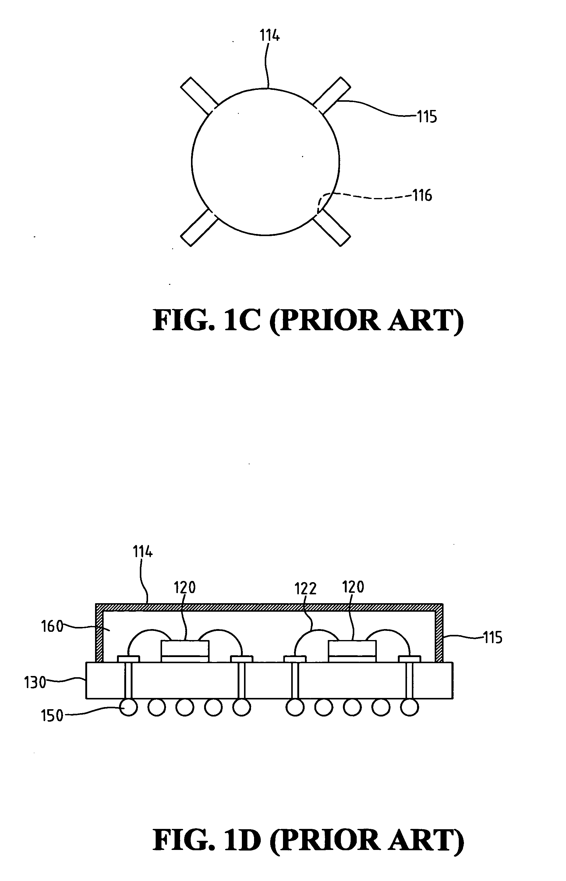
[0060] Then, a single metal sheet is cut or molded into a specific shape. As shown in FIGS. 6B and 6C, heat slug 514 can be either of the round shape or a rectangular shape, and antenna feed metal sheet 512 can be one of the support elements. In the following bending step, the single metal sheet is bended along dashed line 516, as shown in FIGS. 6B and 6C, to make heat slug 514 being perpendicular to support elements 515.
[0061] The next ...
third embodiment
[0065]FIGS. 8A-8G show the fabricating process of the present invention.
[0066] First, at least a chip 720 is attached to upper surface 731 of substrate 730, on which antenna signal transmission line 721 and a plurality of metal belts 740 are already formed. Wire bond 722 is then formed to connect chip 320, as shown in FIG. 8A.
[0067] Then, the metal sheets are cut or molded into a specific shape, respectively. Because the structure of this embodiment uses double metal sheets, each of the metal sheets must be cut or molded into a different shape in accordance with the design. As the example shown in FIGS. 8B and 8C, antenna 711 has a rectangular or round shape, while antenna feed metal sheet 712 may have a triangular or rectangular shape. As for heat slug 714 and its plurality of support elements 715, the metal sheet can be cut or molded into a shape as shown in FIG. 1C.
[0068] The metal sheets are then bended so that heat slug 714 and support elements 715, and connection metal sheet...
PUM
 Abstract
Description
Claims
Application Information
 - R&D
- Intellectual Property
- Life Sciences
- Materials
- Tech Scout
- Unparalleled Data Quality
- Higher Quality Content
- 60% Fewer Hallucinations
Browse by: Latest US Patents, China's latest patents, Technical Efficacy Thesaurus, Application Domain, Technology Topic, Popular Technical Reports.
© 2025 PatSnap. All rights reserved.Legal|Privacy policy|Modern Slavery Act Transparency Statement|Sitemap|About US| Contact US: help@patsnap.com


