Fabricating a three-dimensional object

a three-dimensional object and fabrication technology, applied in the direction of additive manufacturing processes, manufacturing tools, instruments, etc., can solve the problems of degrading the quality of objects, affecting the production efficiency of objects, and easily displaced powder particles in the surface layer

Active Publication Date: 2006-04-06
HEWLETT PACKARD DEV CO LP
View PDF11 Cites 45 Cited by
  • Summary
  • Abstract
  • Description
  • Claims
  • Application Information

AI Technical Summary

Benefits of technology

[0018]FIGS. 13-15 are illustrations showing an embodiment...

Problems solved by technology

A common problem faced when creating three-dimensional objects from dry powder is that powder particles in the surface layer are easily displaced by activities required to apply binder to the powder.
One significant cause of the dry powder disturbance is kinetic energy of the binder drops hitting the surface layer at a speed usually in the range of 5-20 m/sec.
This “cratering” manifests itself in increased surface roughness of the printed object and, hence, degrades the object quality.
In some extreme cases (low mass/density powder particles, heavy and fast drops) the “cratering” makes creation of a smooth surface finish very difficult to achieve.
Anothe...

Method used


Image

  • Fabricating a three-dimensional object
  • Fabricating a three-dimensional object
  • Fabricating a three-dimensional object

Examples


Embodiment Construction

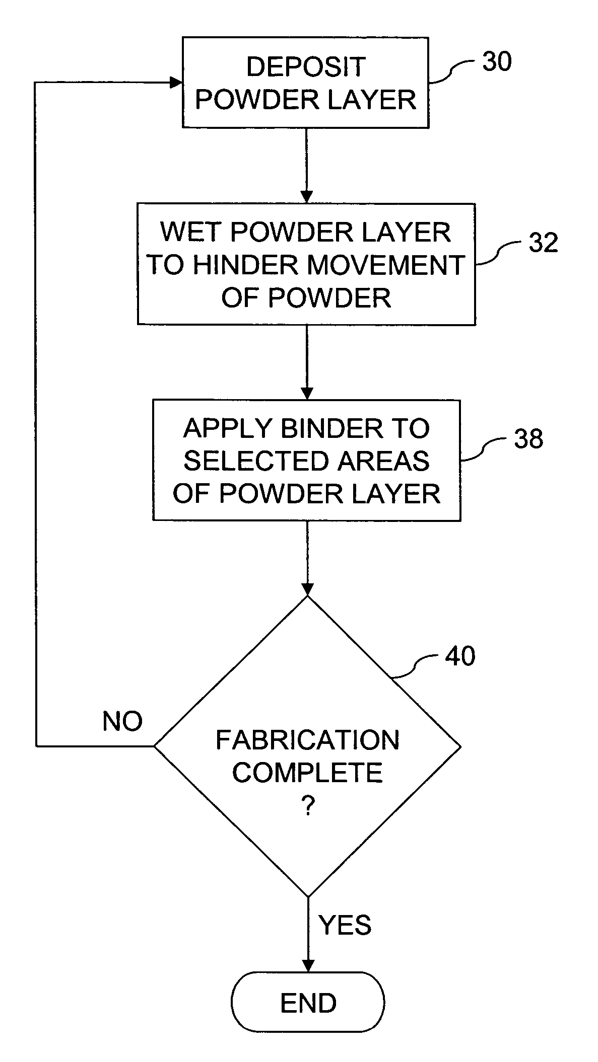
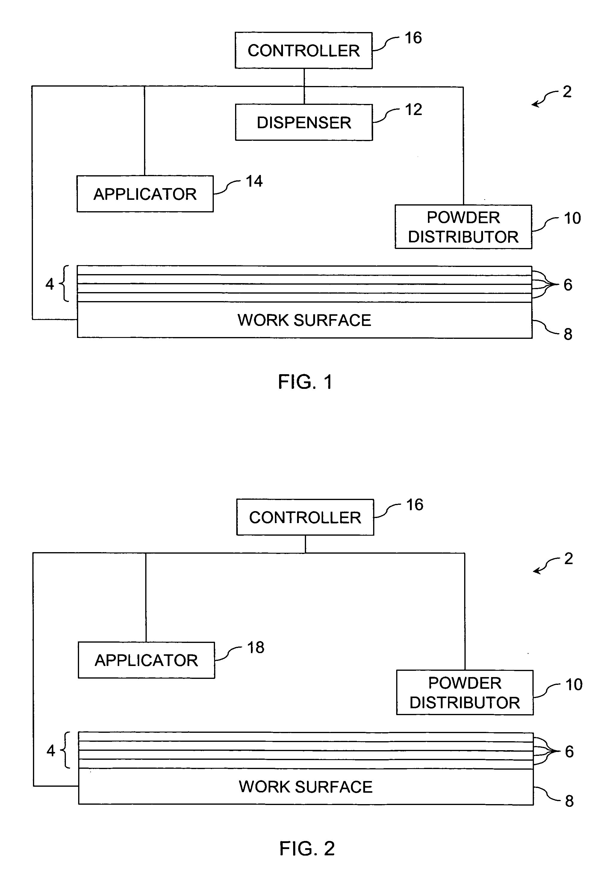
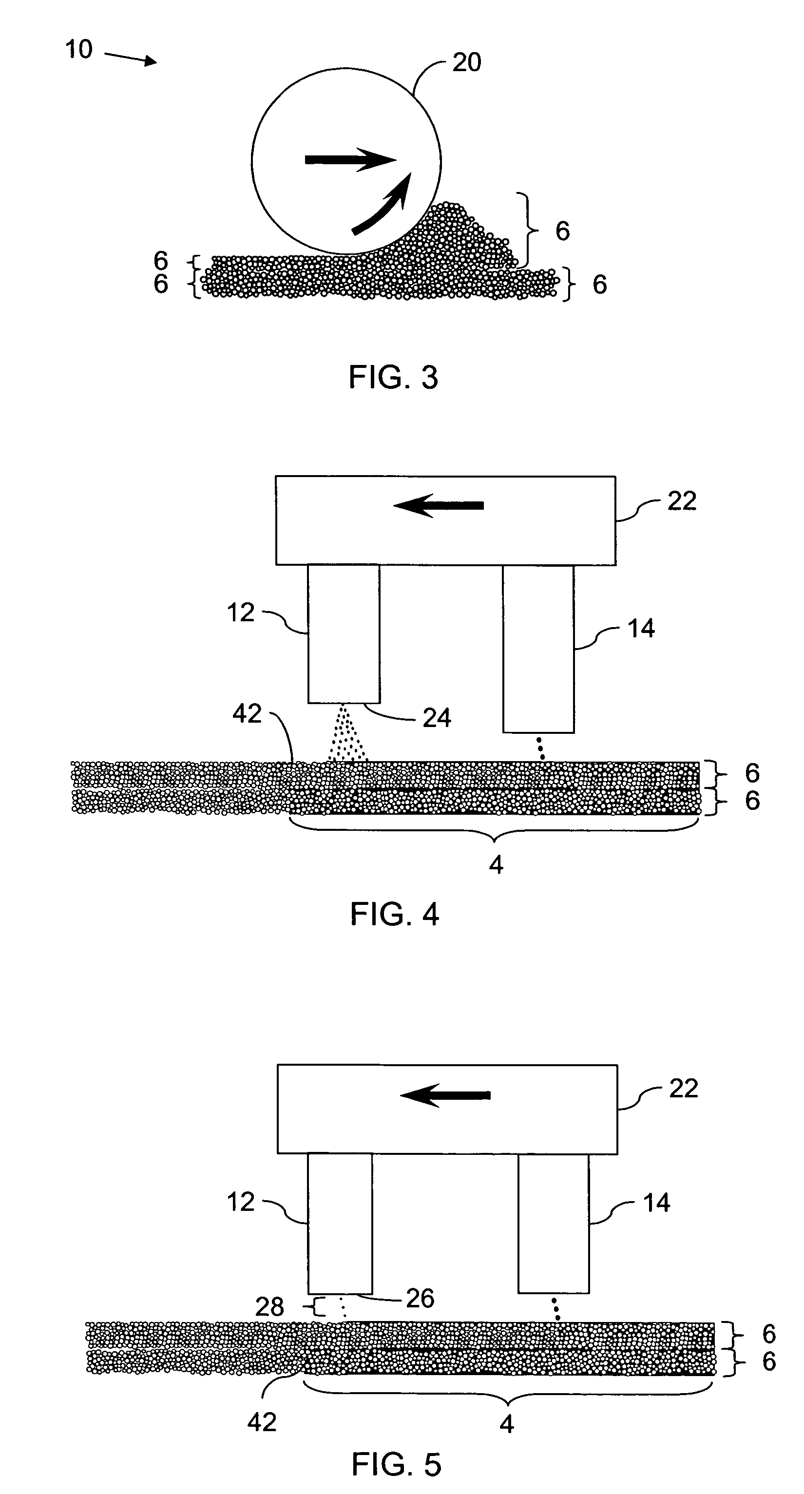
[0019]FIG. 1 shows one embodiment of solid freeform fabrication tool 2 for making a three-dimensional object 4 from powder layers 6. The height of each layer 6 is exaggerated to better illustrate the invention. In one embodiment, solid freeform fabrication tool 2 includes work surface 8, powder distributor 10, dispenser 12, and applicator 14. Controller 16 coordinates the operation of work surface 8, powder distributor 10, dispenser 12, and applicator 14.

[0020] Work surface 8 is any surface or platform upon which object 4 may be supported while being fabricated. Powder distributor 10 is any apparatus or system configured to deposit powder layers 6 onto work surface 8. In one embodiment, as shown in FIG. 3, powder distributor 10 includes a rotating roller 20 which spreads an amount of powder to a desired thickness as it moves above the build work surface.

[0021] Referring again to FIG. 1, in one embodiment, work surface 8 is moveable with respect to powder distributor 10 for precise...


PUM

PropertyMeasurementUnit
Areaaaaaaaaaaa
Distanceaaaaaaaaaa
Hydrophobicityaaaaaaaaaa

Abstract

A three-dimensional object is fabricated from powder. A powder layer is deposited. The powder layer is selectively wetted to hinder movement of the powder. A binder is applied to selected areas of the powder layer to harden the areas of the powder layer. The steps are repeated until the three-dimensional object is fabricated.

Description

CLAIM OF PRIORITY [0001] This application claims the benefit of U.S. Provisional Application No. 60 / 614,512, filed on Sep. 29, 2004, entitled FABRICATING A THREE-DIMENSIONAL OBJECT, and having express mail label number EL871865041 US (Attorney Docket Number 200309780-1).BACKGROUND OF THE INVENTION [0002] One technique for fabricating three-dimensional objects is to deposit layers of dry powder and bind selected portions of the layers together. A common problem faced when creating three-dimensional objects from dry powder is that powder particles in the surface layer are easily displaced by activities required to apply binder to the powder. [0003] One significant cause of the dry powder disturbance is kinetic energy of the binder drops hitting the surface layer at a speed usually in the range of 5-20 m / sec. On impact, binder drops create small “craters” on the non-bound powder surface. This “cratering” manifests itself in increased surface roughness of the printed object and, hence, ...

Claims


Application Information

Patent Timeline
IPC IPC(8): B28B1/14
CPCB28B1/00B28B1/001B29C67/0081B33Y10/00B33Y30/00B29C64/165
Inventor HUNTER, SHAWN D.KASPERCHIK, VLADEK P.NIELSEN, JEFFREY ALLENCOLLINS, DAVID C.CRUZ-URIBE, TONY
Owner HEWLETT PACKARD DEV CO LP
Why Eureka
Try Eureka