Switched-capacitor circuits with reduced finite-gain effect

a switched capacitor and finite-gain technology, applied in the field of integrated circuits, can solve the problems of inability to precisely fabricate resistance values, error is introduced into the circuit, and the realization of modern op amps falls short of ideal characteristics, so as to achieve the effect of minimizing the final gain

Active Publication Date: 2006-04-06
TEXAS INSTR INC
View PDF8 Cites 69 Cited by
  • Summary
  • Abstract
  • Description
  • Claims
  • Application Information

AI Technical Summary

Benefits of technology

[0015] It is therefore an object of this invention to provide a switched-capacitor operational amplifier circuit in which the finite gain effect is minimized.
[0016] It is a further object of this invention to provide such a circuit in which modest op amp gain values can still provide excellent precision operation.
[0017] It is a further object of this invention to relax the tradeoff between op amp gain and switching speed, such that a higher speed op amp can be used in a precise application, such as a pipelined analog-to-digital converter (ADC).
[0022] According to another aspect of the invention, a pipelined ADC is constructed using the inventive op amp circuits. Estimates of the op amp circuit outputs are fed ahead to the next stages of the pipeline, and the clock phase timing of the pipelined stages is arranged to accept the estimates, enabling high performance operation.

Problems solved by technology

Switched capacitor circuits are particularly attractive in modern integrated circuits, because of the ability of the manufacturing technology to physically construct high-quality capacitors in relatively small integrated circuit “chip” area; in contrast, integrated circuit resistors tend to occupy a great deal of chip area, and are difficult to fabricate with precise resistance values.
To the extent that the actual realization of modern op amps fall short of the ideal characteristics, however, error is introduced into the circuit.
This defeats the “virtual” ground assumption for the ideal op amp, and thus introduces error into the circuit.
In addition, the switching speed of conventional op amps is also not instantaneous, which also introduces error into the circuit.
It is well known in the art that conventional op amp designs involve a tradeoff between switching speed and gain, such that a high switching speed can only be attained by sacrificing op amp gain, and vice versa.
Because of these effects, the circuit application must either tolerate non-ideal op amp characteristics, or circuit techniques must be developed to reduce the effect of these non-ideal characteristics.
If the input voltage changes between phases, however, the correction is not accurate without including a third clock phase to obtain the exact correction.
Accordingly, it is believed that the performance of these known op amp circuits is limited.

Method used


Image

  • Switched-capacitor circuits with reduced finite-gain effect
  • Switched-capacitor circuits with reduced finite-gain effect
  • Switched-capacitor circuits with reduced finite-gain effect

Examples


Embodiment Construction

[0031] The present invention will be described in connection with its preferred embodiment, namely as implemented into various circuits used in a pipelined analog-to-digital converter (ADC). This particular implementation is described because it is contemplated that this invention is especially beneficial in such an application. However, it is also contemplated that this invention can be advantageously used in a wide range of operational amplifier circuits. Accordingly, it is to be understood that the following description is provided by way of example only, and is not intended to limit the true scope of this invention as claimed.

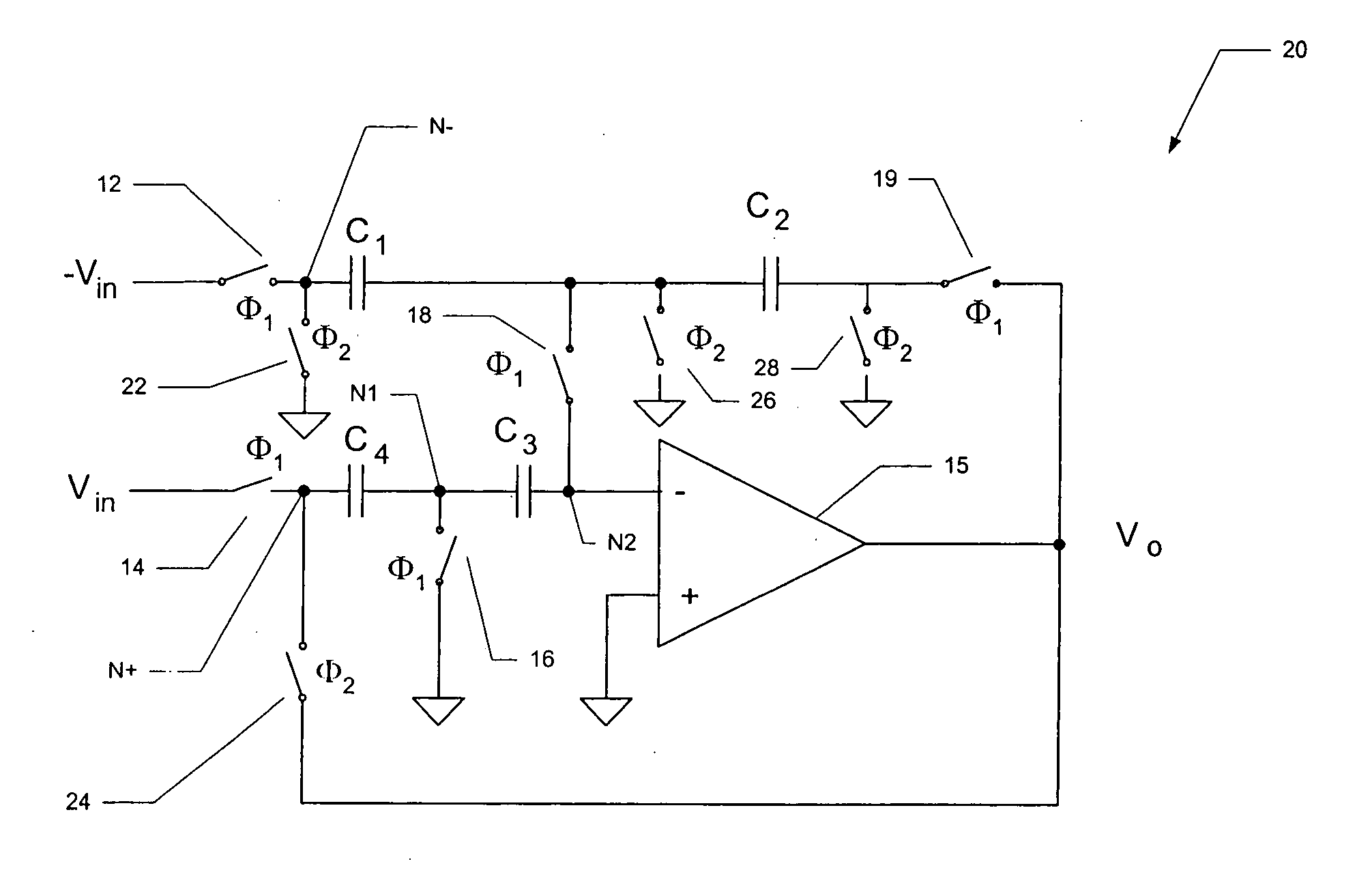
[0032] Referring now to FIG. 3, sample-and-hold circuit 20 constructed according to a preferred embodiment of the invention will now be described. As shown in FIG. 3, sample-and-hold circuit 20 includes operational amplifier (“op amp”) 15, which has its non-inverting input at ground, and its inverting input connected to a node N2 connected to one side of c...


PUM


Abstract

Operational amplifier circuits (20, 30) including error capacitors (C3, C13) for storing finite gain effect error voltages for correction of output voltages of the circuits (20, 30), are disclosed. The circuits (20, 30) are operated in a sample clock phase to produce an approximation of the output voltage, using negative polarity versions of the input voltages to the circuit. The approximate output voltage is used to produce and store an error voltage, corresponding to the differential voltage at the input of the operational amplifier (15, 25), relative to virtual ground. This error voltage is then subtracted from the input voltage applied in the operate clock phase, to correct for the finite gain effect. A pipelined analog-to-digital converter (50) using the disclosed operational amplifier circuits (20, 30) is also disclosed.

Description

CROSS-REFERENCE TO RELATED APPLICATIONS [0001] Not applicable. STATEMENT REGARDING FEDERALLY SPONSORED RESEARCH OR DEVELOPMENT [0002] Not applicable. BACKGROUND OF THE INVENTION [0003] This invention is in the field of integrated circuits, and is more specifically directed to analog switched-capacitor circuits utilizing operational amplifiers. [0004] A common building block in modern analog or mixed-signal analog electronic circuits is the operational amplifier. As is fundamental in the art, operational amplifiers can be readily implemented into analog circuits for performing a wide range of functions, including analog multiplication, analog integration, active filtering, and analog-to-digital conversion, to name a few. These widely ranging functions derive from the ideal characteristics of an operational amplifier (or “op amp”), namely infinite open loop gain, infinite input impedance, and zero output impedance. These ideal characteristics are used to advantage in conventional feed...

Claims


Application Information

Patent Timeline
Patent Type & Authority Applications(United States)
IPC IPC(8): H03F1/02H03F3/00H03F3/45
CPCH03F3/005H03F3/45977
Inventor MALOBERTI, FRANCOK. KINYUA, MARTIN
Owner TEXAS INSTR INC
Why Eureka
Try Eureka