Liquid crystal display of ocb or va mode

Inactive Publication Date: 2006-04-06
FUJIFILM CORP
View PDF4 Cites 32 Cited by
  • Summary
  • Abstract
  • Description
  • Claims
  • Application Information

AI Technical Summary

Benefits of technology

[0016] The inventor has further studied and finally found that the unified polarizing plate, in which an optical compensatory sheet and a polarizing plate is unified, can be prevented from changing its optical character and accordingly from leaking light by thinning two cellulose acetate films used as protective films provided on both sides of the polarizing membrane.
[0017] An object of the present invention is to improve qualities of images given by a liquid crystal display of OCB mode, by means of a polarizing plate comprising in order an optically anisotropic layer formed from liquid crystal compound, a first transparent protective film of cellulose acetate film, a polarizing membrane, a second transparent protective film, and a light-diffusing layer.
[0018] Another object of the invention is to improve qualities of images given by a liquid cryst

Problems solved by technology

The first cause is distortion induced by change of external temperature and humidity.
The expansion or shrinkage is limited since the film is fixed, and accordingly the compensatory sheet is distorted to change its optical characters.
The other is distor

Method used


Image

  • Liquid crystal display of ocb or va mode
  • Liquid crystal display of ocb or va mode
  • Liquid crystal display of ocb or va mode

Examples


Example

EXAMPLE 1

(Preparation of Cellulose Acetate Film used as the First Transparent Protective Film)

[0238] The following components were poured into a mixing tank, and stirred and heated to dissolve each component. Thus, a cellulose acetate solution was prepared. Cellulose acetate solutionCellulose acetate having acetic80weight partsacid content of 60.9% (linter)Cellulose acetate having acetic20weight partsacid content of 60.8% (linter)Triphenyl phosphate7.8weight partsBiphenyl diphenyl phosphate3.9weight partsMethylene chloride300weight partsMethanol45weight parts

[0239] Independently, 4 weight parts of cellulose acetate having acetic acid content of 60.9% (linter), 25 weight parts of the following retardation increasing agent, 0.5 weight part of silica fine particles (mean size: 20 nm), 80 weight parts of methylene chloride and 20 weight parts of methanol were poured into another mixing tank, and stirred and heated to prepare a retardation increasing agent solution.

(Retardation-Inc...

Example

EXAMPLE 2

(Production of Viewer-Side Polarizing Plate for VA Mode)

[0271] Iodine was adsorbed on a stretched polyvinyl alcohol film to prepare a polarizing membrane.

[0272] The second transparent protective film (on which the diffusing layer was provided in Example 1) was saponified and laminated on one surface of the polarizing membrane with polyvinyl alcohol adhesive, so that the second transparent protective film (cellulose acetate film) might be contact with the membrane.

[0273] The first transparent protective film prepared in Example 1 was laminated on the other surface of the membrane with polyvinyl alcohol adhesive, so that the slow axis of the film might be parallel to the transmission axis of the polarizing membrane.

[0274] Thus, a viewer-side polarizing plate for VA mode was produced.

(Production of Backlight-Side Polarizing Plate)

[0275] Iodine was adsorbed on a stretched polyvinyl alcohol film to prepare a polarizing membrane.

[0276] The first transparent protective f...


PUM


Abstract

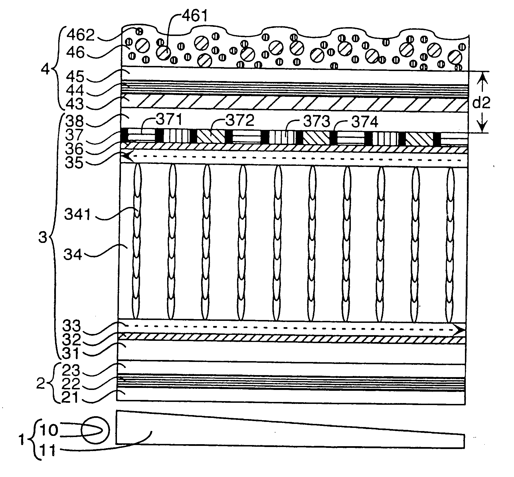
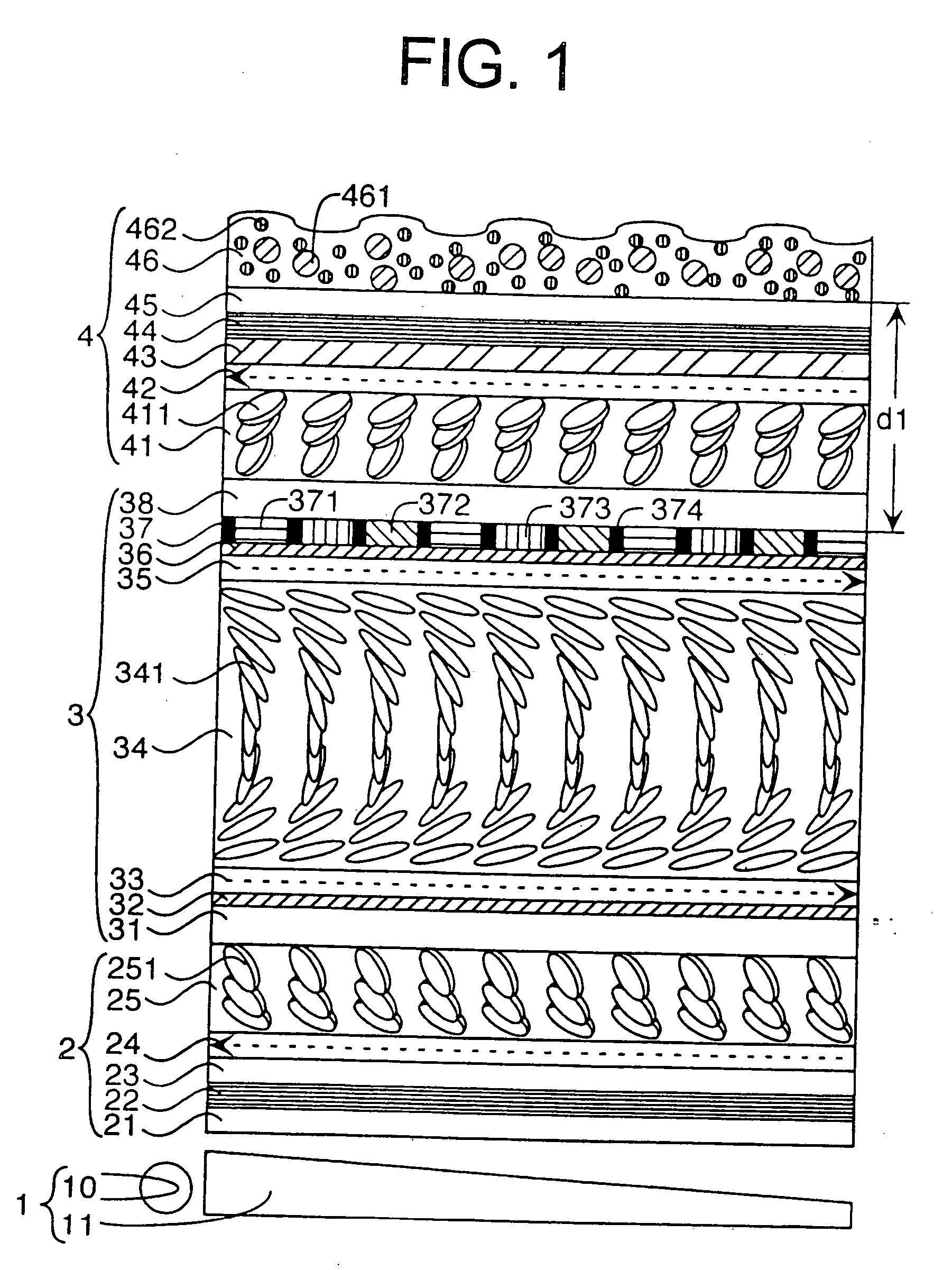
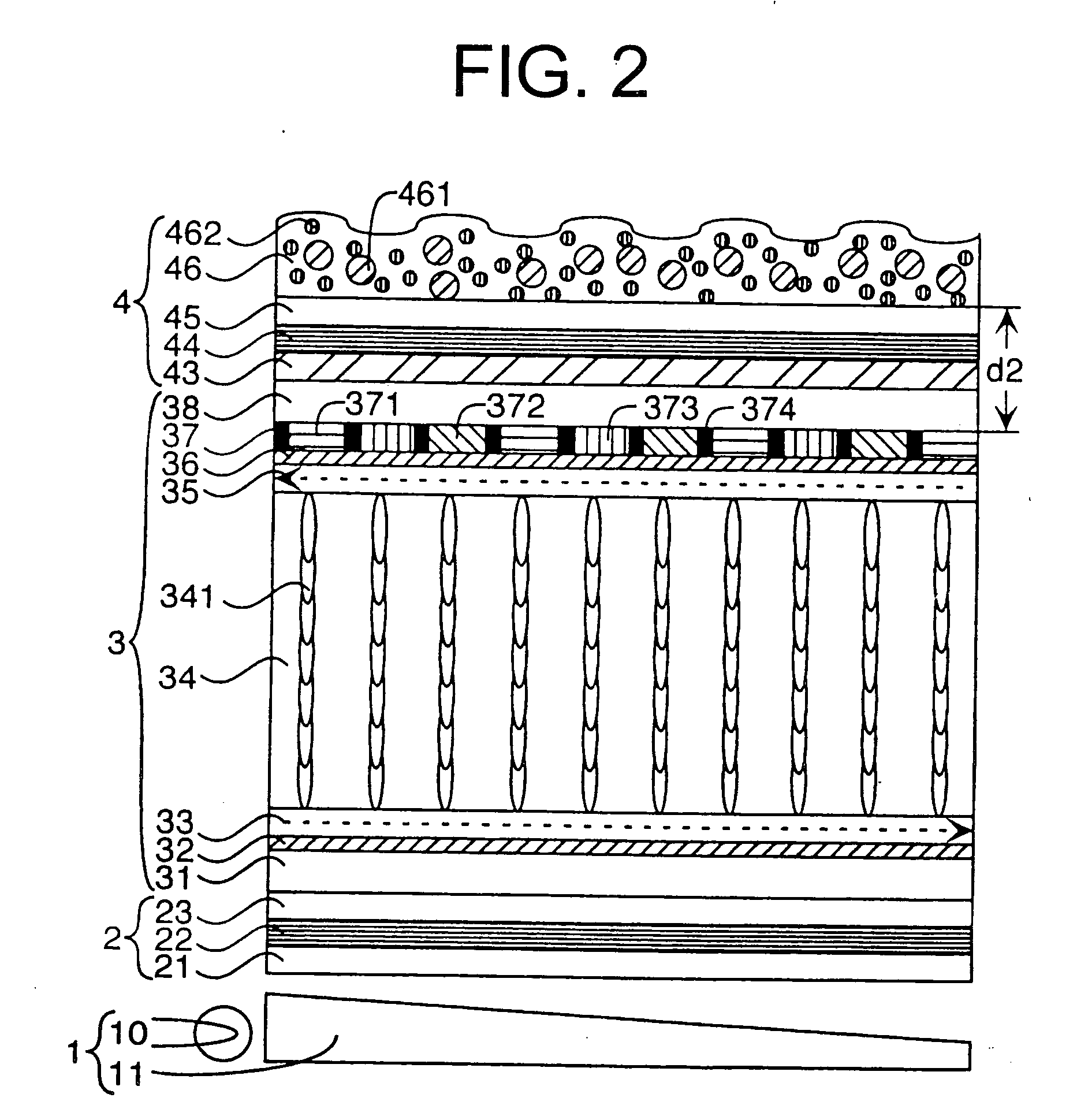
A liquid crystal display of OCB mode or VA mode comprises a backlight unit, a backlight-side polarizing plate, a liquid crystal cell of OCB mode or VA mode, and a viewer-side polarizing plate in order. The viewer-side polarizing plate comprises a first transparent protective film, a polarizing membrane, a second transparent protective film and a light-diffusing layer in order. In the liquid crystal display of OCB mode, an optically anisotropic layer is formed from liquid crystal compound on the first transparent protective film. The first transparent protective film is a cellulose acetate film having a Re retardation value of 20 to 70 nm and a Rth retardation value of 100 to 500 nm. The light-diffusing layer comprises transparent resin and transparent fine particles dispersed therein. The transparent resin and the transparent fine particles have refractive indices that are different from each other.

Description

FIELD OF INVENTION [0001] The present invention relates to a liquid crystal display of OCB or VA mode using a polarizing plate. BACKGROUND OF INVENTION [0002] A liquid crystal display comprises a polarizing plate and a liquid crystal cell. Various display modes of the liquid crystal cell have been proposed, for example TN mode and STN mode, which are now popularly used. In a liquid crystal display of TN or STN mode, an optical compensatory sheet is generally provided between the polarizing plate and the liquid crystal cell to improve the viewing angle and qualities of the displayed image. [0003] U.S. Pat. Nos. 4,583,825 and 5,410,422 disclose a liquid crystal display comprising a liquid crystal cell of OCB (Optically Compensatory Bend) mode, in which alignment of rod-like liquid crystal molecules in upper part is essentially reversal (symmetrical) to the alignment of molecules in lower part. Since the liquid crystal molecules are symmetrically aligned in the upper and lower parts, t...

Claims


Application Information

Patent Timeline
IPC IPC(8): G02F1/1335G02F1/1333G02B5/30F21V8/00F21Y101/00G02F1/13363G02F1/139
CPCG02F1/133504G02F1/133528G02F1/133634G02F1/1393G02F1/1395G02F2413/105G02F1/1335G02F1/13363G02F1/139
Inventor ITO, YOJI
Owner FUJIFILM CORP
Why Eureka
Try Eureka