
Exposure method and apparatus, and method for fabricating device

a technology of fabricating device and exposure method, which is applied in the field of exposure technology, can solve the problems of insufficient resolution in the direction, insufficient resolution in the densely massed contact hole with fine pitch, and insufficient resolution in the resolution of large contact hole pitch, so as to improve the resolution and depth of focus, improve the resolution, and increase the amount of light

Active Publication Date: 2006-04-06
NIKON CORP
View PDF10 Cites 107 Cited by
  • Summary
  • Abstract
  • Description
  • Claims
  • Application Information

AI Technical Summary

Benefits of technology

[0011] And the second object of the present invention is to provide an exposure technology for transferring the pattern, which is arranged in one direction periodically and is substantially isolated (pattern densely massed in one direction) in terms of the orthogonal direction, with high resolution.
[0091] Furthermore, if the pattern formed at the mask is periodically arranged along a predetermined first axis and includes the one direction dense pattern which is substantially isolated in the direction of the second axis orthogonal to the first axis, by arranging the three areas in which the amount of light is great with distance in the parallel direction to the first axis, it is able to transfer the one direction dense pattern with high resolution both directions of arranging the one direction dense pattern to periodical and isolatable ones. Further, in the present invention, with setting the state of polarization of the optical beam oriented from the three areas in which the amount of light is great, it might be to improve the resolution and the like for a predetermined pattern.

Problems solved by technology

For that reason, however, it is disadvantage that when using the deformed illumination system, the resolution is not sufficient for the contact hole with large pitch; while when using the small σ illumination system, the resolution is not sufficient for the densely massed contact hole with fine pitch.
However, it is disadvantage that the resolution is not sufficient in the direction in which the pattern can be regarded as the isolated pattern, with using the traditional deformed illumination system for this purpose, while it is not sufficient in the direction in which the pattern is arranged with the fine pitch, with using the small σ illumination system.

Method used


Image

  • Exposure method and apparatus, and method for fabricating device
  • Exposure method and apparatus, and method for fabricating device
  • Exposure method and apparatus, and method for fabricating device

Examples


first embodiment

THE FIRST EMBODIMENT

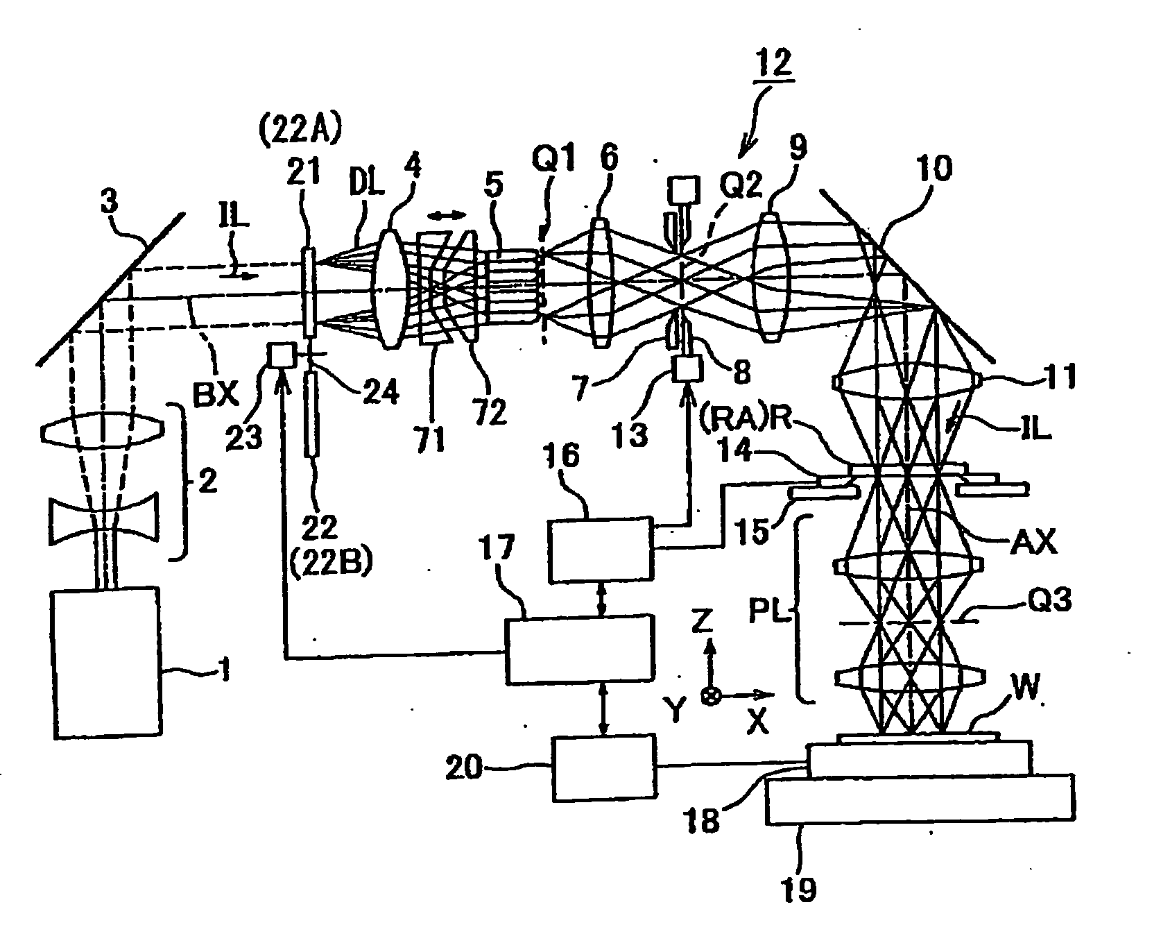
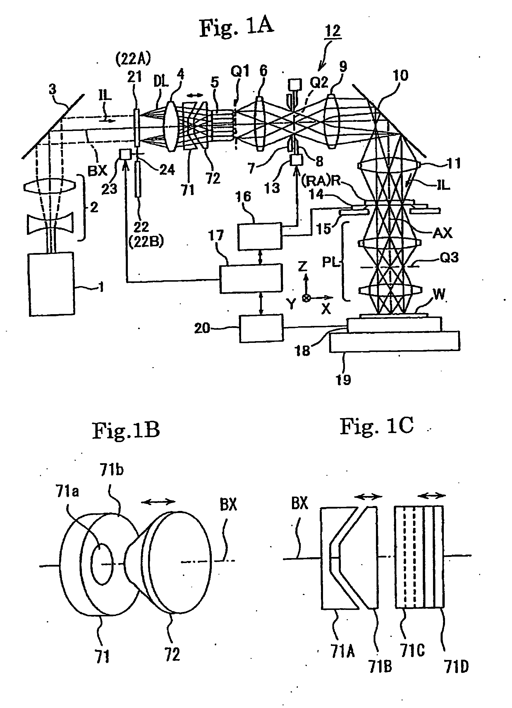
[0116] A preferably first embodiment will be described accompanying FIGS. 1 to 9, as follows:

[0117] This embodiment applies the present invention when doing exposure with the projection exposure apparatus using an illumination system which has a fly′ eye lens as an optical integrator (uniformizer or homogenizer).

[0118]FIG. 1A shows a composition of the projection exposure apparatus of this embodiment, in FIG. 1A, a KrF excimer laser light source (wave-length 248 nm) is used as an exposure light source 1. In addition, the laser light sources such as an ArF excimer laser light source (wave-length 193 nm), a F2 laser light source (wave-length 157 nm), a Fr2 laser light source (wave-length 146 nm), or an Ar2 laser light source (wave-length 126 nm); or high frequency generating apparatus such as a high frequency generating light source of a YAGI laser or a solid laser (for example semiconductor laser etc.) can be used as a exposure light source 1.

[0119] An illumina...

second embodiment

THE SECOND EMBODIMENT

[0181] Nest, the second embodiment according to the present invention will be described accompanying FIG. 10 to FIG. 17. Also in this embodiment, the exposure is fundamentally performed by using the scan exposure type projection optical apparatus in FIG. 1A. In this embodiment, however, instead of the diffractive optical element 21 in FIG. 1A, a diffractive optical element 22A (described bellow in detail) having different characteristic is used. Accordingly, the diffractive optical element 22A, the first prism 71, and the second prism 72 are corresponding to an optical member for setting a predetermined distribution of amount of light. In this embodiment, as with the first embodiment, the prism 71, 72 (or the first prism 71 only) are used as movable prism.

[0182] Further, as shown FIG. 10, it is allow using a pair of prisms 71A, 71B shaped like a letter V which has diffractive power to one direction and has not diffractive power to orthogonal direction, as the m...

third embodiment

[0229] Next, there will be explained a third embodiment of the present invention referring to FIG. 18 to FIG. 21. The first embodiment uses member including the diffraction optical devices 21, 22 as the optical member for setting the predetermined amount of light distribution, on the contrary, this embodiment uses the aperture stop as the optical member thereof, and in FIG. 18, there is attached the same symbol to a portion corresponding to FIG. 1A to omit its detailed description.

[0230]FIG. 18 shows a configuration of the projection exposure apparatus of this embodiment, in this FIG. 18, the illumination light IL from the exposure light source 1, is made incident into the fly-eye lens 5 via the beam expander 2 and the mirror 3. There is disposed the aperture stop (a stop) 42 as the optical member for obtaining the predetermined amount of light distribution at the emission plane Q1 as the predetermined plane, in the emission plane Q1 (the pupil plane of the illumination system 12) ...


PUM


Abstract

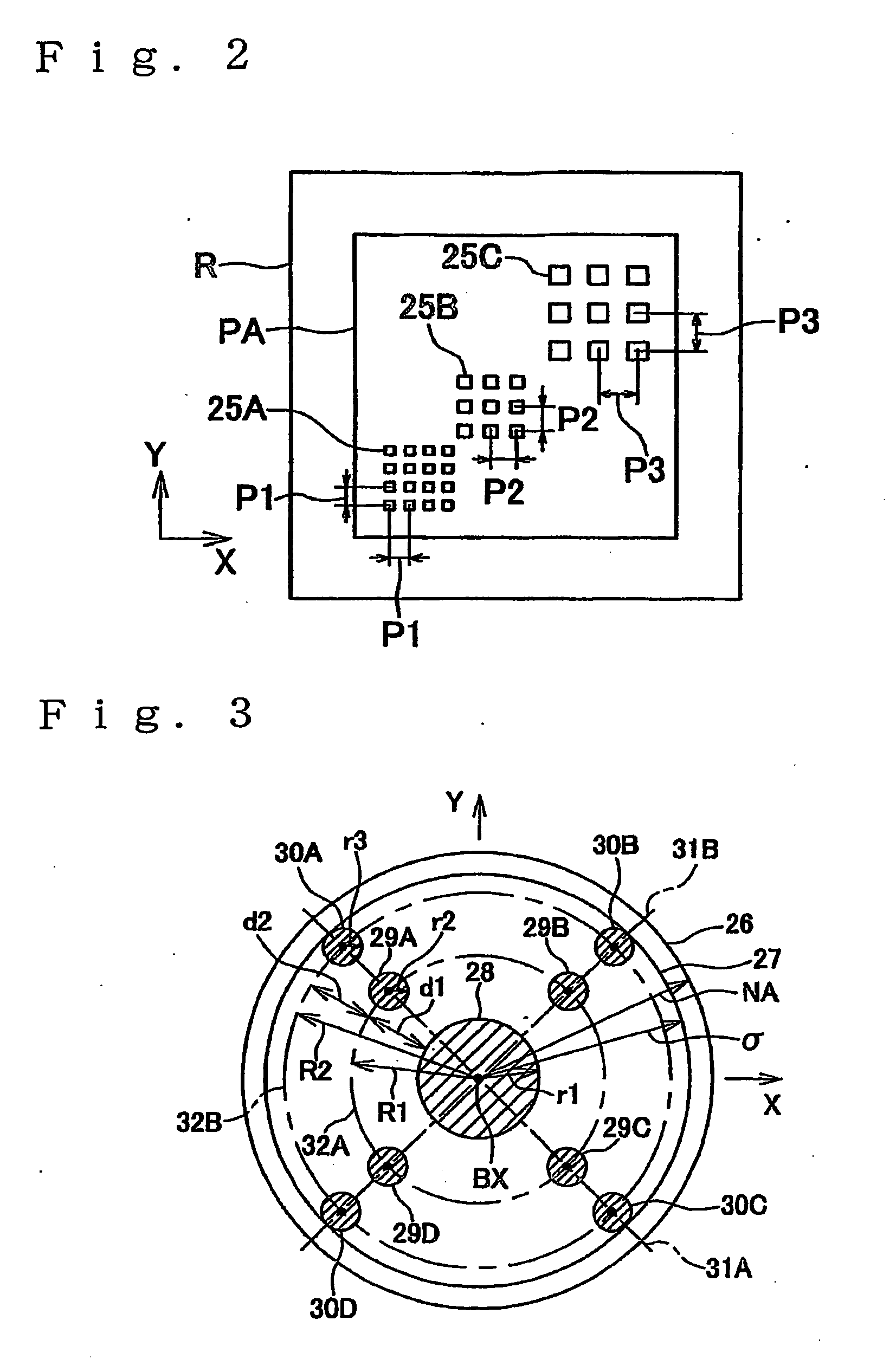
An exposure method and apparatus simultaneously transfer patterns with various pitches with high resolution. On the pupil surface of an illumination system, nine areas are set. The nine areas are a first area including the optical axis, four second areas each smaller than the first area and arranged along a first circumference surrounding the first area, and four third areas each smaller than the first area and arranged along a second circumference surrounding the first circumference and arranged along a second circumference. The distribution of intensity of light over the pupil surface is so set that the intensities of light over the nine areas are approximately equal to one another, and the intensity of light over the other area is smaller than those over the nine areas. This distribution of intensity of light is set using a diffraction optical element or a diaphragm.

Description

[0001] This is a Continuation of International Application No. PCT / JP2004 / 004522 filed Mar. 30, 2004. The entire disclosure of the prior application is hereby incorporated by reference herein in its entirety.TECHNICAL FIELD [0002] The present invention relates to an exposure technology used to transfer mask-pattern on substrates such as wafers in a lithography process for fabricating various kinds of devices such as semiconductor elements, liquid crystal displays, thin-film magnetic heads and, more particularly to an exposure technology using an illuminating technology related to the so-called deformed illumination. Further, the present invention relates to a technology for fabricating the device using the exposure technology. BACKGROUND ART [0003] The apparatus for the projection exposure of the batch exposure system such as the step-and-repeat system or the scan exposure system such as the step-and-scan system have been used to transfer the pattern of the reticle (or photo-mask et...

Claims


Application Information

Patent Timeline
IPC IPC(8): G03B27/72G03F7/20
CPCG03B27/42G03F7/701G03F7/70191G03F7/70158G03F7/70566G03F7/70108G03F7/2006H01L21/0275G03F7/70091
Inventor KUDO, TAKEHITOHIRUKAWA, SHIGERU
Owner NIKON CORP
Learn More