Method of detecting and correcting errors for a memory and corresponding integrated circuit

Inactive Publication Date: 2006-04-06
STMICROELECTRONICS SRL
View PDF22 Cites 17 Cited by
  • Summary
  • Abstract
  • Description
  • Claims
  • Application Information

AI Technical Summary

Benefits of technology

[0011] An object of the invention is to correct and detect errors in memories by using single error correcting codes (for example of the SEC-DED type) or single error detecting only codes (for example, of

Problems solved by technology

The evaluation of the characteristics of the corrector blocks must consider the increase in area introduced by the cells storing the control bits, the area occupied by the coders/decoders, and the delays produced by the passage of the data through these blocks which penalize the memory access times. The integration of the correcting circuits then usually results from a compromise made between these various criteria and the gain in reliability, which does not generally make it possible to integrate overly complex codes.
Although these codes are simple and exhibit a low overhead of area, their drawback is that they only constitute error detection codes and do not perform corrections.
In systems using correcting codes of the SEC-DED type, if the number of errors exceeds unity, then correction is not possible and the information item

Method used


Image

  • Method of detecting and correcting errors for a memory and corresponding integrated circuit
  • Method of detecting and correcting errors for a memory and corresponding integrated circuit
  • Method of detecting and correcting errors for a memory and corresponding integrated circuit

Examples


first embodiment

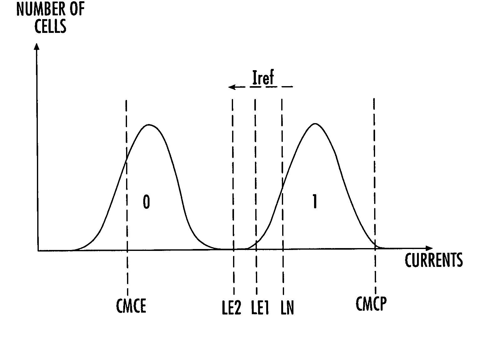
[0043] An object of the invention is aimed at carrying out several error detections-corrections for the n data items of the code block, obtained by modifying the level of the reference current Iref. For example, FIG. 6 illustrates such a correction system in the case where the mechanism of degradation of the data by loss of charge is significant and leads in particular to a shift in the population of the cells. Such is the case in particular for floating gate nonvolatile memories.

[0044] Thus, a first read is carried out with the reference level LN corresponding to a normal read. The set of n elements of the code block thus read provides a first result. If the detection code indicates the presence of an error, a second read using a reference level LE1 that is less than the level LN is carried out. With the read reference current being lower, the number of errors decreases. Also, these operations are iteratively repeated while decreasing the reference current Iref with each iteration ...

second embodiment

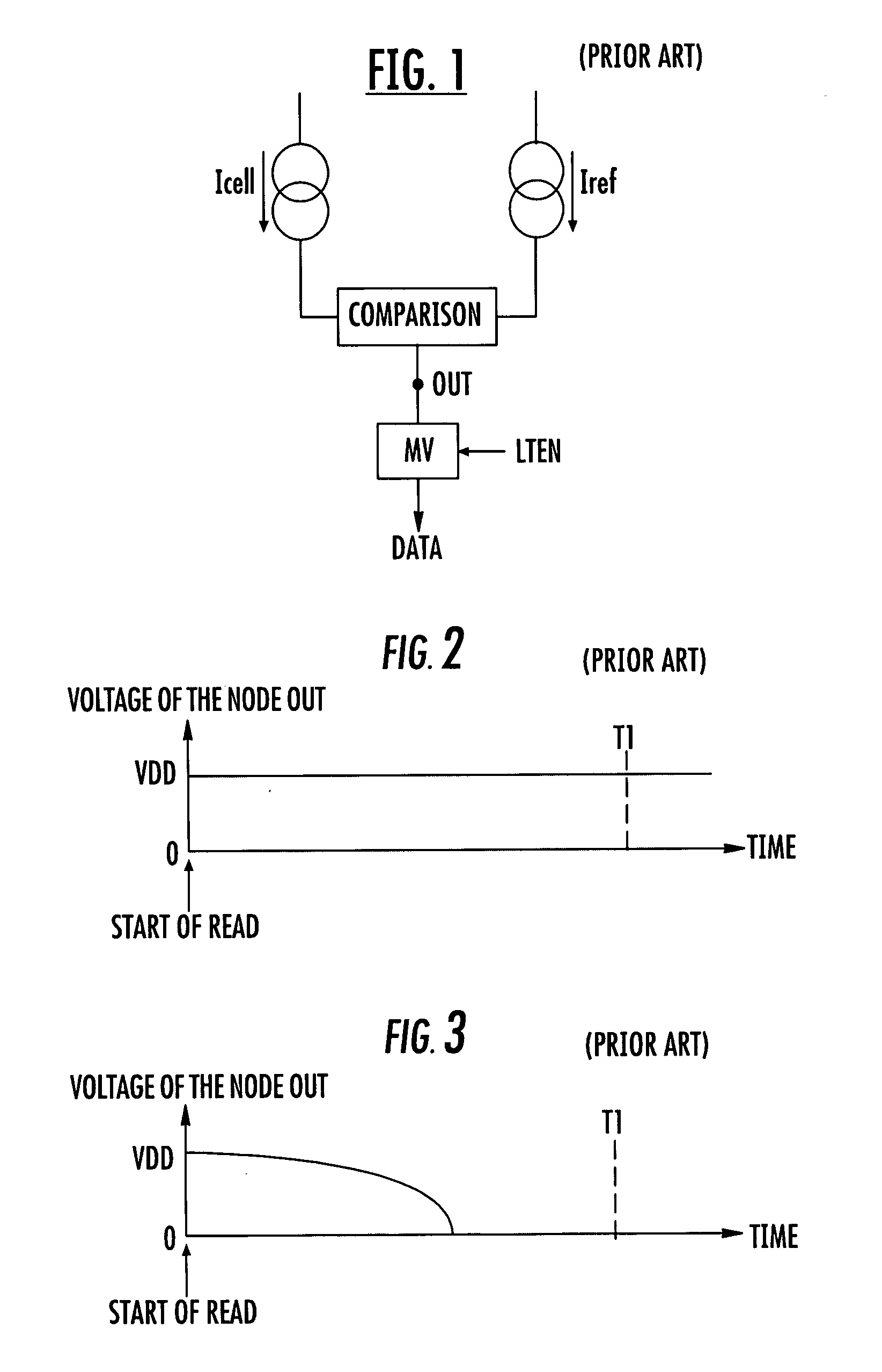
[0058] The invention is not limited to the modes of implementation and embodiments just described. Specifically according to the invention, the instant T1 of consideration of the result of the comparison, that is to say the duration of reading, is modified as read parameter, rather than the reference current. This is illustrated in FIG. 10. In this figure, curve C3 represents the profile of the voltage of the node OUT of a programmed cell (logic “1”) degraded during a read with a reference current Iref having the standard level LN.

[0059] It is seen that by taking into consideration the result of the comparison at the standard instant T1, a logic “0” is obtained, that is to say an erroneous reading result. On the other hand by decreasing the duration of read, that is to say by performing the recording of the result of the comparison at earlier instants TE, for example at the instant TE2, this reading error is eliminated.

[0060] Care should be taken not to decrease the duration of rea...


PUM


Abstract

A method is for detecting and correcting errors for a memory storing at least one code block including information data and control data. The method includes reading and decoding each element of the at least one code block to deliver an information item representative of a number of errors in the at least one code block. The method further includes, when the number of errors exceeds one, modifying a parameter of the read by a chosen value, and performing a reading and decoding of the at least one code block again to obtain a new error information item.

Description

FIELD OF THE INVENTION [0001] The invention relates to the detecting and correcting of errors in the reading of data stored in a memory, such as, for example, a nonvolatile memory of “FLASH / EEPROM” type or of a magnetic memory of MRAM type. BACKGROUND OF THE INVENTION [0002] The use of error correcting codes is now widespread in memory systems. They are intended to correct defects occurring in the manufacture of circuits by supplementing or replacing the traditional redundancy columns, and to correct defects occurring during the operation of the memory. [0003] For example, dynamic memory circuits (DRAMs) increasingly comprise error correcting code blocks to increase manufacturing yields or to correct errors produced from the alpha particles bombardment that occurs during the life of the product. Nonvolatile memories of the flash / EEPROM type are also increasingly associating their control circuits with error correcting systems, such as in the field of multi-level / bit memories, to inc...

Claims


Application Information

Patent Timeline
IPC IPC(8): G11C29/00H03M13/09H03M13/19H03M13/35H03M13/37
CPCH03M13/09H03M13/19H03M13/35H03M13/37
Inventor GENDRIER, PHILIPPECANDELIER, PHILIPPEFOURNEL, RICHARD
Owner STMICROELECTRONICS SRL
Why Eureka
Try Eureka