Method and system for electrical and mechanical power generation using Stirling engine principles

a technology of stirling engine and principle, applied in the direction of mechanical power devices, machines/engines, mechanical apparatus, etc., can solve the problems of low efficiency, high cost of manufacture, complex design of stirling engine, etc., and achieve the effect of improving efficiency

Inactive Publication Date: 2006-04-13
SILVER GUY +1
View PDF42 Cites 11 Cited by
  • Summary
  • Abstract
  • Description
  • Claims
  • Application Information

AI Technical Summary

Benefits of technology

[0005] The present invention provides a heat engine enclosed in a housing having two zones maintained at different temperatures. The first zone (“hot zone”) receives heat energy from an external power source. The second zone (“cold zone”) is connected to the hot zone, such that a fluid (e.g., air, water, or any other gas or liquid) filling the two zones can circulate between the two zones. The expansion of the fluid in the hot zone and the compression of the fluid in the cold zone provide a symmetrical thermodynamic cycle to drive a turbine to provide a power output. The fluid may be pressurized to enhance efficiency.

Problems solved by technology

The designs of these Stirling engine are typically complex and include numerous moving parts.
Consequently, these designs are costly to manufacture and their efficiencies are low.

Method used


Image

  • Method and system for electrical and mechanical power generation using Stirling engine principles
  • Method and system for electrical and mechanical power generation using Stirling engine principles
  • Method and system for electrical and mechanical power generation using Stirling engine principles

Examples


Embodiment Construction

[0019] The present invention provides a heat engine, operating under Stirling engine principles, for converting heat energy into mechanical and electrical energy. The electrical energy derived using a heat engine of the present invention may be in the form of alternating current (AC) power, for immediate distribution, or in the form of direct current (DC) to allow storage or other applications.

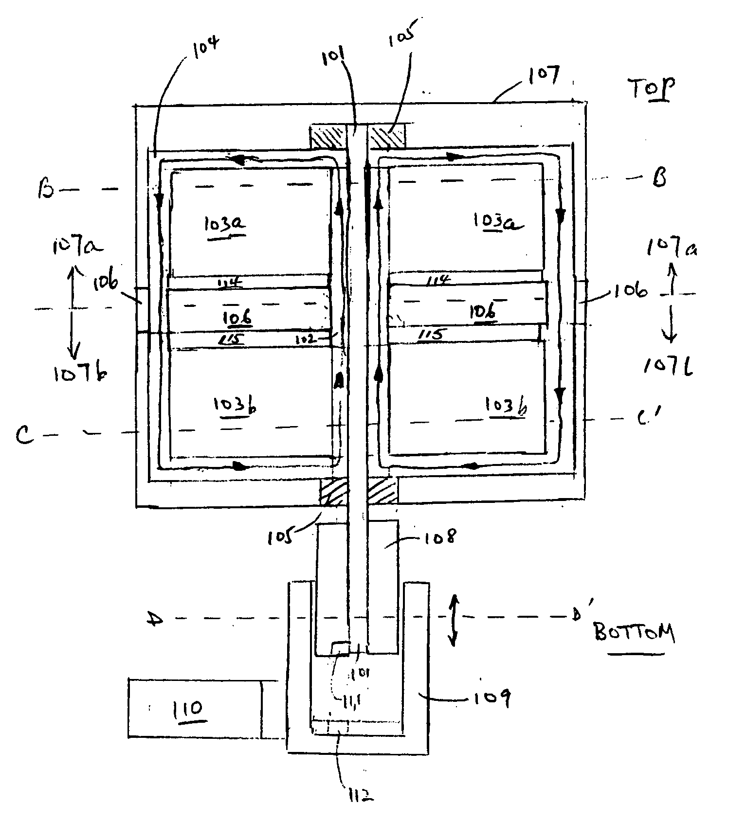
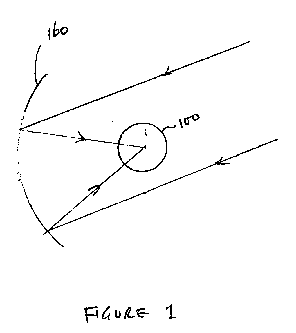
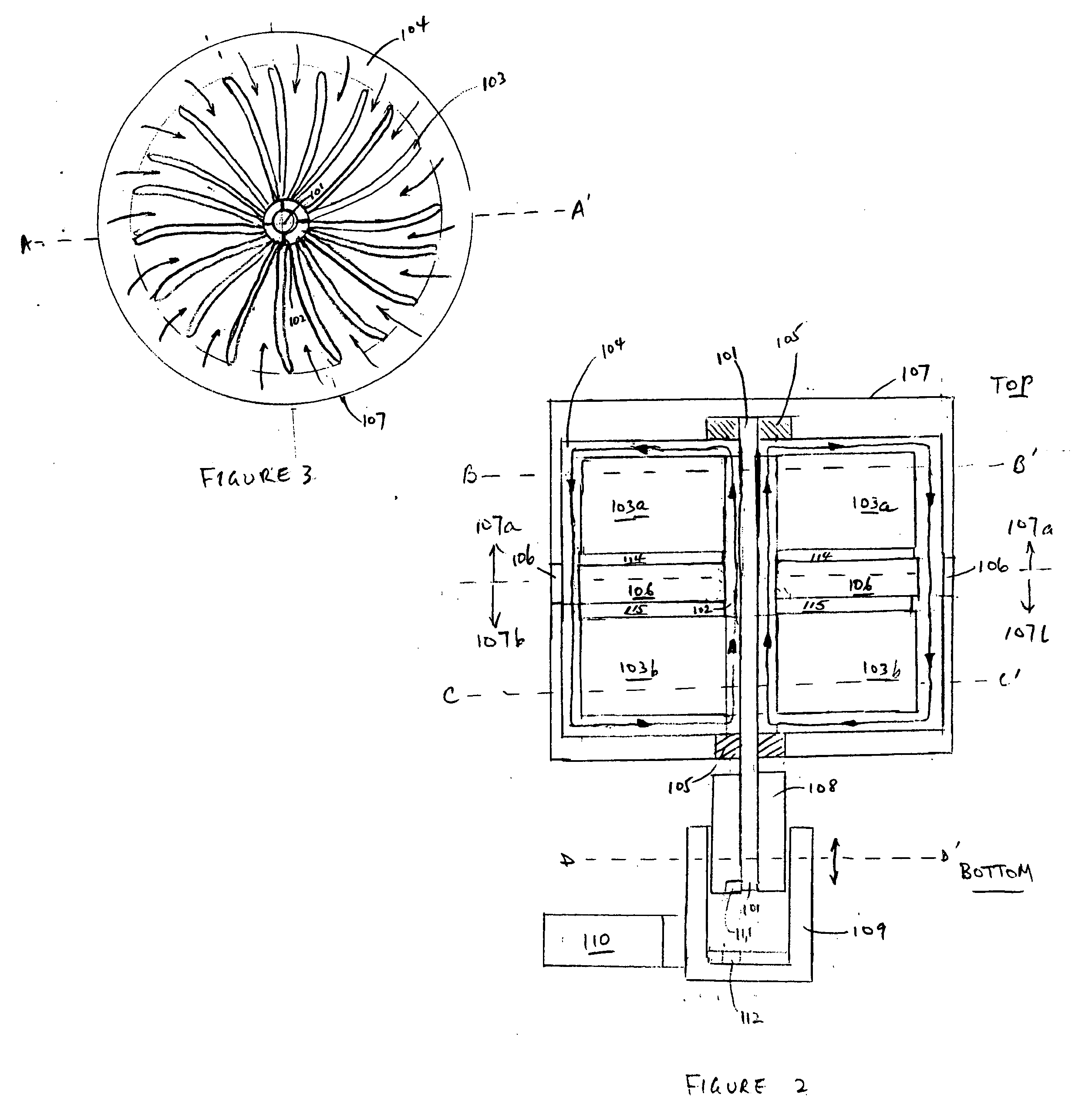
[0020] The heat engine of the present invention may operate with any source of heat energy, including solar, geothermal, fossil, landfill recovered or other fuels. FIG. 1 shows heat engine 100 receiving solar energy from a solar reflector 160, in accordance one embodiment of the present invention. One embodiment of heat engine 100 of FIG. 1 is shown in a cross section view in FIG. 2. As shown in FIG. 2, heat energy 100 includes an external housing 107 which seals a hot portion or zone 107a and a cold portion or zone 107b. In this detailed description, the terms “hot” and “cold” are relative. ...


PUM


Abstract

A heat engine enclosed in a housing has two chambers maintained at different temperatures. The first chamber (“hot chamber”) receives heat energy from an external power source. The second chamber (“cold chamber”) is connected to the hot chamber by two conduits, such that a fluid (e.g., air, water, or any other gas or liquid) filling the two chambers can circulate between the two chambers. The expansion of the fluid in the hot chamber and the compression of the fluid in the cold chamber drive a turbine to provide a power output. The fluid may be pressurized to enhance efficiency. In one embodiment, the turbine propels an axle in a rotational motion to transmit the power output of the heat engine to an electrical generator outside of the heat engine's housing. In one embodiment, the turbine includes a first set of blades and a second set of blades located in the hot chamber and the cold chamber, respectively. The blades may each have a flat profile having two unequal surfaces, such that the turbine rotates in preferentially in one direction.

Description

BACKGROUND OF THE INVENTION [0001] 1. Field of the Invention [0002] The present invention relates to applying Stirling engine principles to the design and use for power conversion equipment. In particular, the present invention relates to applying Stirling engine principles for electrical and mechanical power generation, especially in the direct current (DC) mode or in the alternating current (AC) modes. [0003] 2. Discussion of the Related Art [0004] The Stirling engine is a heat engine that operates by converting the heat energy which flows between two portions of the heat engine having different temperatures into mechanical power. A typical Stirling engine uses the heat energy to drive a coordinated and reciprocating motion of a set of pistons. Numerous designs of Stirling engines can be found in the prior art, including: U.S. Pat. Nos. 6,578,359, 6,050,092, 6,195,992, 6,735,946 and 6,164,263. The designs of these Stirling engine are typically complex and include numerous moving p...

Claims


Application Information

Patent Timeline
Patent Type & Authority Applications(United States)
IPC IPC(8): F02G1/04F01B29/10F01K23/06
CPCF02C1/10F03G6/068Y02E10/46
Inventor SILVER, GUYWU, JUINERONG
Owner SILVER GUY
Why Eureka
Try Eureka