Electro-optical device and electronic apparatus

Active Publication Date: 2006-04-13
BOE TECH GRP CO LTD
View PDF5 Cites 36 Cited by
  • Summary
  • Abstract
  • Description
  • Claims
  • Application Information

AI Technical Summary

Benefits of technology

[0008] An advantage of the invention is that it provides an electro-optical device and an electronic apparatus with a reduced thickness, when an electro-optical device having both a display section and a sound-production body is provided in an electronic apparatus.
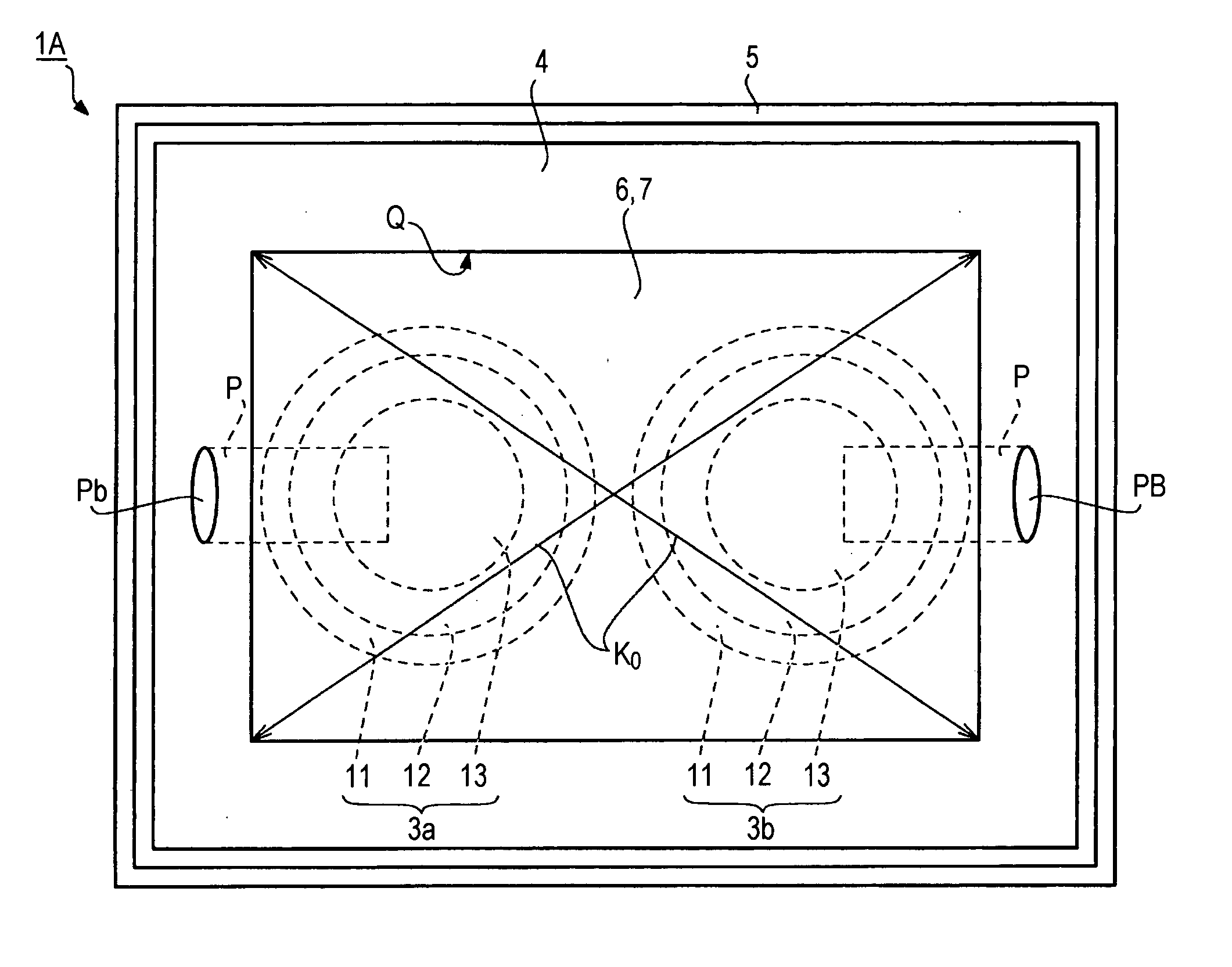
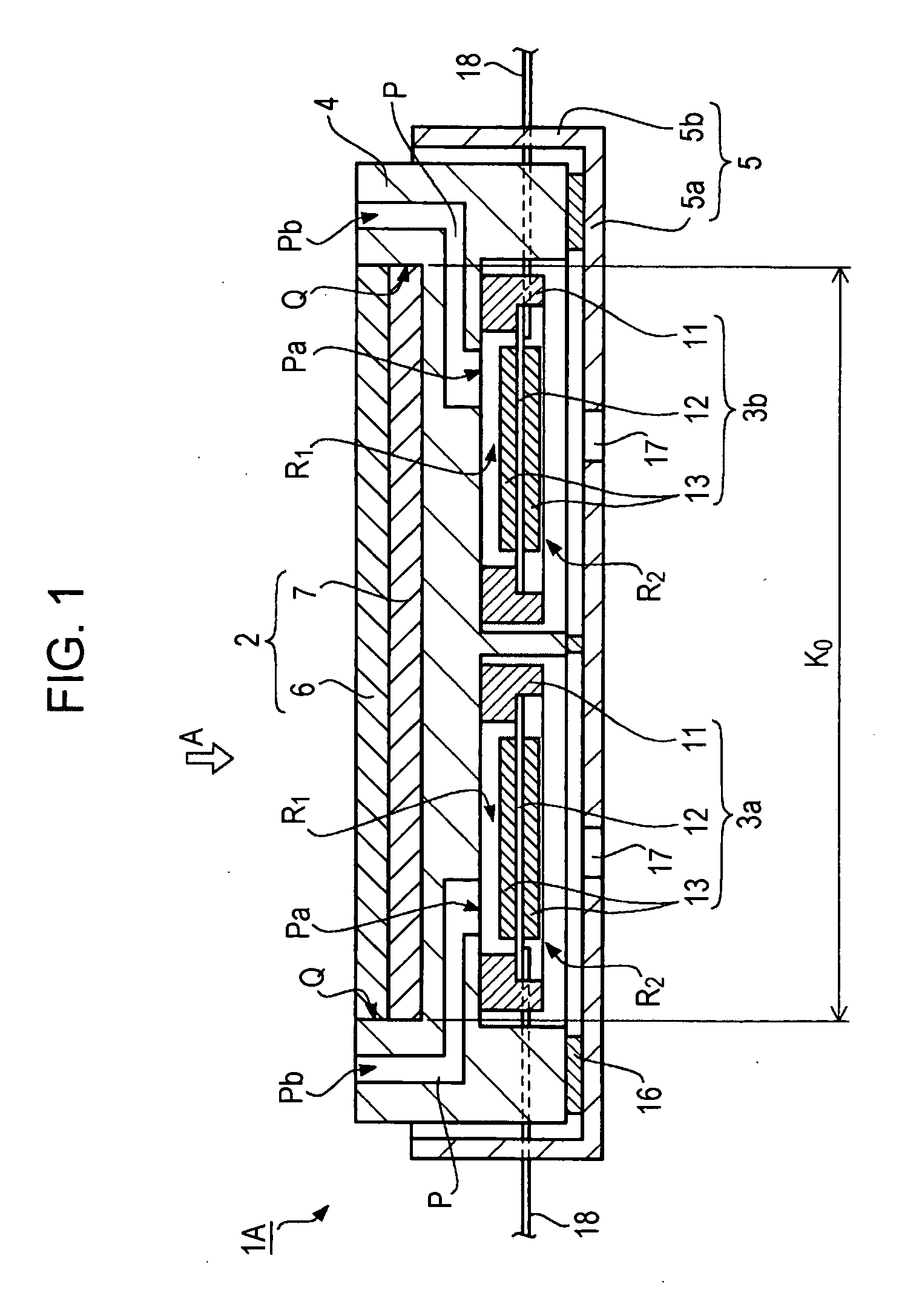
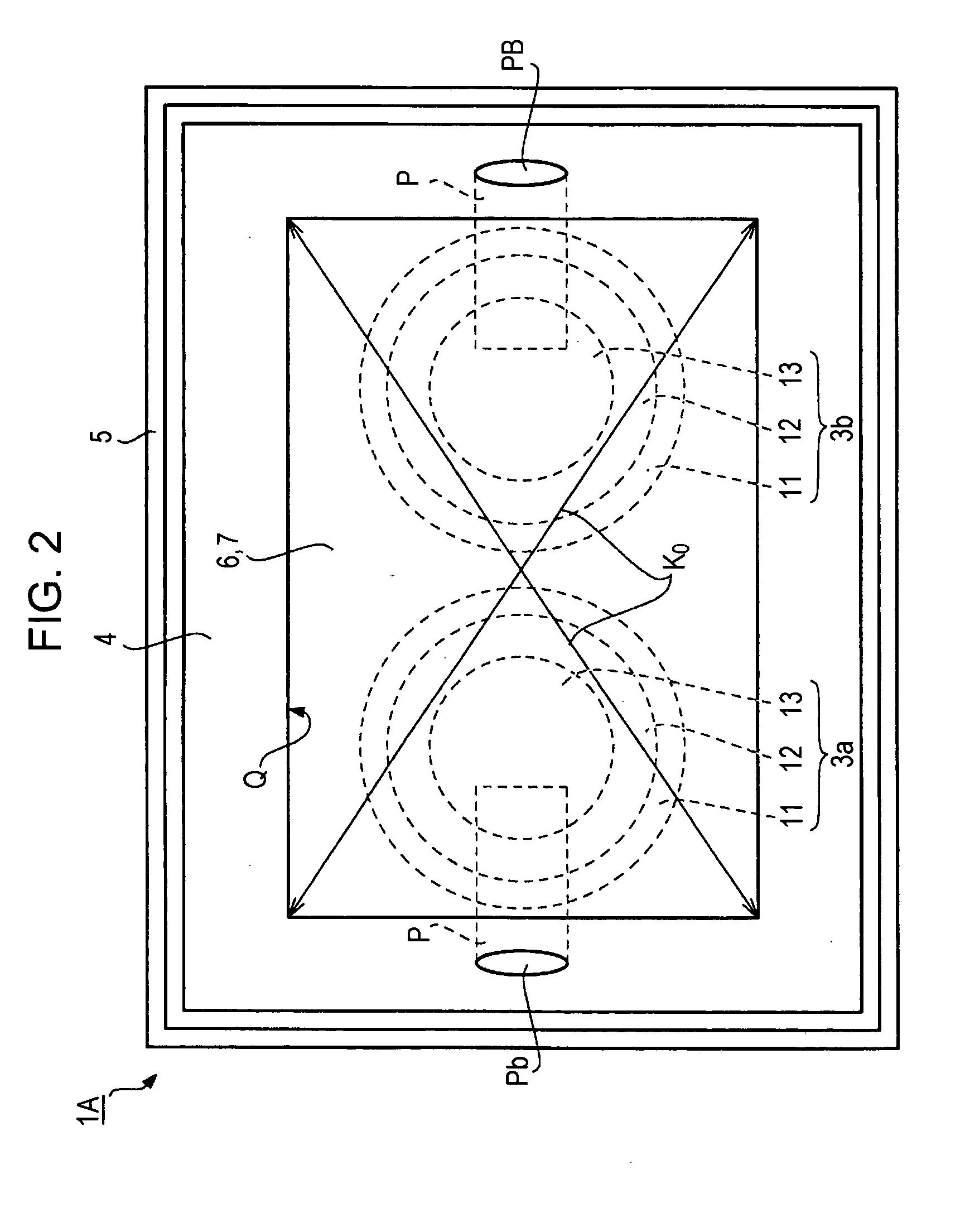
[0009] According to a first aspect of the invention, an electro-optical device includes a display section that has a display region, a plurality of sound-production bodies that are disposed to overlap the display section and produce sound, and a first frame that is disposed between the display section and the sound-production bodies and holds the display section. The first frame forms air spaces for the plurality of sound-production bodies. In the first frame, sound-guiding paths and sound-releasing holes are formed to correspond to the plurality of sound-production bodies.
[0010] In the above-described configuration, the ‘display section’ can be constituted by any display unit. As such a display unit, a liquid crystal display device, an EL display device, a plasma display device, and other display devices can be used. Further, the ‘sound-production body’ can be constituted by a speaker, for example. Further, the first frame can be made of plastic, a metal, or the like. Since the first frame forms the air spaces for the plurality of sound-production bodies, the first frame may have a complex shape. In such a case, the first frame is preferably formed by a resin molding method with plastic as a material.
[0011] According to the electro-optical device having the above-described configuration, the display section is held by the first frame, the first frame is disposed between the display section and the sound-production bodies, and the air spaces for the so

Problems solved by technology

In this case, if the electro-optical device and the plurality of sound-production bodies are disposed to overlap each other in a thicknesswise direction of the electronic apparatus each other, the thickn

Method used


Image

  • Electro-optical device and electronic apparatus
  • Electro-optical device and electronic apparatus
  • Electro-optical device and electronic apparatus

Examples


Example

Second Embodiment of Electro-Optical Device

[0064]FIG. 4 shows an electro-optical device according to another embodiment of the invention. In the electro-optical device 1A shown in FIG. 1, the two speaker units 3a and 3b serving as the sound-production bodies are fixed to the first frame 4. On the contrary, in an electro-optical device 1B shown in FIG. 4, the frames 11 of the two speaker units 3a and 3b are fixed to the bottom wall 5a of the second frame 5, such that the speaker units 3a and 3b are supported by the second frame 5. That is, the first frame 4 supports the liquid crystal display device 2 serving as the display section, and the second frame 5 supports the speaker units 3a and 3b and the first frame 4 separately.

[0065] Moreover, the planar structure of the electro-optical device 1B as viewed from the arrow A direction is the same as the planar structure shown in FIG. 2. Further, in FIG. 4, the same parts as those in the embodiment of FIG. 1 are represented by the same r...

Example

Third Embodiment of Electro-Optical Device

[0068]FIG. 5 shows an electro-optical device according to still another embodiment of the invention. In this embodiment, the same parts as those in the embodiment shown in FIG. 1 are represented by the same reference numerals, and thus the descriptions thereof will be omitted. In the electro-optical device 1A shown in FIG. 1, the speaker units 3a and 3b serving as the sound-production bodies are planarly arranged so as not to overlap each other. On the contrary, in an electro-optical device 1C shown in FIG. 5, two speaker units 3a and 3b are arranged so as to partially overlap each other. In a case of the electro-optical device 1C, as shown in FIG. 6, all the two speaker units 3a and 3b fall within the spatial region K0 in the vertical direction of the surface on the display region of the liquid crystal panel 6.

[0069] In FIG. 5, the inside of the first frame 4 has a stepped shape. One speaker unit 3b is provided at a step close to the liqu...

Example

Fourth Embodiment of Electro-Optical Device

[0071]FIG. 7 shows an electro-optical device according to a further embodiment of the invention. In this embodiment, the same parts as those in the embodiment shown in FIG. 1 are represented by the same reference numerals, and thus the descriptions thereof will be omitted. In the electro-optical device 1C shown in FIG. 5, the two speaker units 3a and 3b serving as the sound-production bodies are arranged so as to partially overlap each other. On the contrary, in an electro-optical device 1D shown in FIG. 7, the two speaker units 3a and 3b are entirely arranged so as to overlap each other. In a case of the electro-optical device 1D, as shown in FIG. 8, all the two speaker units 3a and 3b fall within the spatial region K0 in the vertical direction of the surface on the display region of the liquid crystal panel 6.

[0072] In this electro-optical device 1D, all the two speaker units 3a and 3b are arranged so as to overlap each other, and thus ...


PUM


Abstract

An electro-optical device includes a display section that has a display region, a plurality of sound-production bodies that are disposed to overlap the display section and produce sound, and a first frame that is disposed between the display section and the sound-production bodies and holds the display section. The first frame forms air spaces for the plurality of sound-production bodies. In the first frame, sound-guiding paths and sound-releasing holes are formed to correspond to the plurality of sound-production bodies, respectively.

Description

BACKGROUND OF THE INVENTION [0001] 1. Technical Field [0002] The present invention relates to an electro-optical device, such as a liquid crystal display device or the like. Further, the invention relates to an electronic apparatus having such an electro-optical device. [0003] 2. Related Art [0004] In recent years, electro-optical devices, such as a liquid crystal display device or the like, have been widely used for an electronic apparatus, such as a portable information terminal or the like. For example, in electronic apparatuses, electro-optical devices are used as display devices for displaying various kinds of information. Electro-optical devices are devices that control optical output states by an electrical input. For example, a liquid crystal display device, an electroluminescent (EL) device, a plasma display device, and other devices may be considered. [0005] The above-described electro-optical device is primarily used to display various kinds of information as images in an...

Claims


Application Information

Patent Timeline
IPC IPC(8): H04R5/02H04R9/06
CPCH04R1/028H04R17/00H04R2499/15
Inventor WADA, HIROSHI
Owner BOE TECH GRP CO LTD
Why Eureka
Try Eureka