Communications receiver method and apparatus

a receiver and communication technology, applied in the field of wireless communication, can solve the problems of inadequate suppression of interference within the receiver chain, limit the compression point of the receiver circuit of the receiver circuit, etc., and achieve the effect of improving the compression point performance of the radiofrequency receiver circuit, reducing amplifier gain, and reducing amplifier gain

Inactive Publication Date: 2006-04-13
TELEFON AB LM ERICSSON (PUBL)
View PDF4 Cites 36 Cited by
  • Summary
  • Abstract
  • Description
  • Claims
  • Application Information

AI Technical Summary

Benefits of technology

[0007] In general, the negative feedback improves the compression point performance of the radiofrequency receiver circuit by decreasing amplifier gain, even where interferer signal frequencies are in-band with the frequency of interest. Further compression point improvements are gained for interferer signal frequencies that are away from the frequency of interest, based on configuring the at least one frequency-dependent circuit to decrease amplifier gain for such frequencies. For example, the at least one frequency-dependent circuit may comprise a resonant collector load circuit for an input stage transistor included in the low-noise amplifier circuit. With this configuration, the resonant collector load circuit can be configured to have decreasing impedance with increasing distance from the frequency of interest. In one embodiment, the resonant, collector load circuit has reduced or minimal impedance at a harmonic of the local oscillator signal frequency to achieve suppression of interferer signal components at that harmonic.

Problems solved by technology

As a general proposition, inadequately suppressed interference within the receiver chain limits the receiver circuit's compression point of the receiver circuit.

Method used


Image

  • Communications receiver method and apparatus
  • Communications receiver method and apparatus
  • Communications receiver method and apparatus

Examples


Embodiment Construction

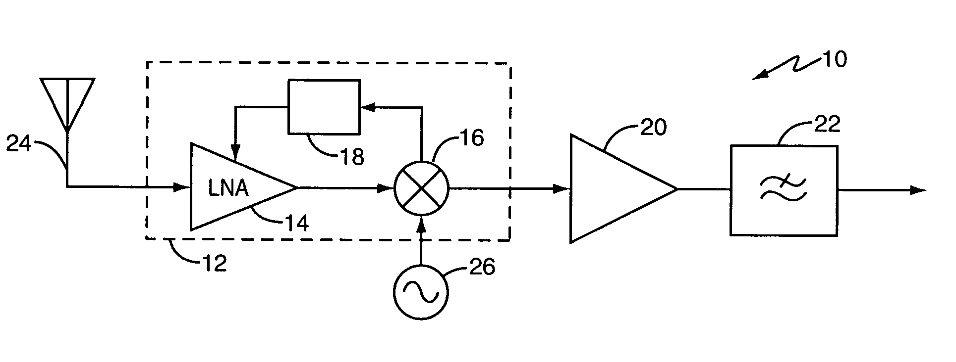
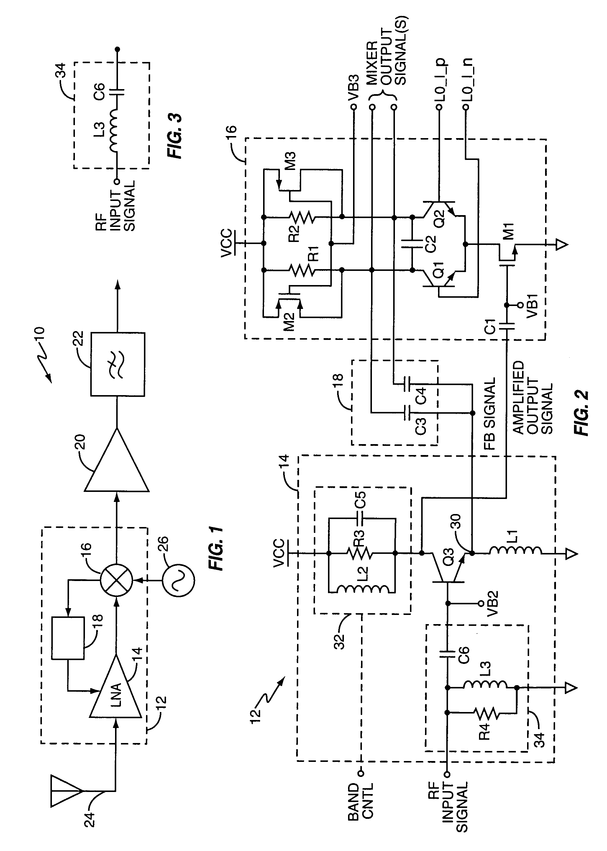
[0022]FIG. 1 illustrates a radiofrequency (RF) receiver 10, including a receiver circuit 12 that comprises a low-noise amplifier (LNA) circuit 14, a mixer circuit 16, and a feedback circuit 18. The receiver 10 further includes a mixer output amplifier 20 and a (low-pass) filter 22, and includes (or is associated with) an antenna 24 and a local oscillator 26.

[0023] In operation, the LNA circuit 14 generates an amplified output signal responsive to an antenna-received RF input signal applied to an amplifier input of the LNA circuit 14. In turn, the mixer circuit 16 generates a mixer output signal responsive to the amplified output signal and one or more local oscillator signals from the local oscillator 26. The mixer output amplifier 20 amplifies the mixer output signal, which, in at least one embodiment, comprises a down-converted baseband signal obtained by frequency-shifting the amplified output signal down to baseband from a given radio carrier frequency.

[0024] The filter 22 fil...


PUM


Abstract

A radiofrequency (RF) receiver circuit and method offer one or more performance improvements, such as an increased input compression point through better out-of-band interference suppression. In one example, an RF receiver circuit includes a low-noise amplifier (LNA) circuit and a mixer. The mixer output signal serves as negative feedback to the LNA circuit for improved compression point performance at interferer frequencies in or out of band with respect to a frequency of interest. Compression point performance is further improved for interferer signal components away from the frequency of interest by including at least one frequency-dependent circuit in the LNA circuit that is configured to reduce amplifier gain for such frequencies. The frequency-dependent circuit(s) may be tunable for different frequencies of interest. Additional improvements may be obtained by including a broadband input matching circuit and/or by including active mixer loads to increase the voltage conversion gain of the RF receiver circuit.

Description

RELATED APPLICATIONS [0001] This application claims priority under 35 U.S.C. § 120 as a continuation-in-part of U.S. application Ser. No. 10 / 746,330, filed on 23 Dec. 2003 and entitled “Mixer with Feedback.” The priority application is expressly incorporated herein by reference.BACKGROUND OF THE INVENTION [0002] The present invention generally relates to wireless communications, and particularly relates to radiofrequency (RF) receivers. [0003] RF receivers must exhibit required sensitivities in the presence of potentially significant interference from unwanted signals. Unwanted signals may be received over the air or may originate locally. For example, mixers used in the down-conversion function of typical RF receivers use square-wave oscillator signals exhibiting large signal components at the third harmonic of the local oscillator frequency. Interference at the third harmonic thus will be down-converted unless attenuated or otherwise rejected within the receiver signal chain. [000...

Claims


Application Information

Patent Timeline
Patent Type & Authority Applications(United States)
IPC IPC(8): H04B1/06H04B1/10H04B1/26
CPCH03F3/191H03F3/50H03F2200/294H03J2200/10H04B1/109H03D7/145H03D7/165H03D2200/0025
Inventor TIRED, TOBIASMATTISSON, SVEN
Owner TELEFON AB LM ERICSSON (PUBL)
Why Eureka
Try Eureka