
Reinforced and drug-eluting balloon catheters and methods for making same

a balloon catheter and a technology of elongation and elongation, which is applied in the field of balloon catheters, can solve the problems of thin wall tubes that have a tendency to crimp or kink, sharp twists and bends, and lose torsional and longitudinal rigidity,

Inactive Publication Date: 2006-04-13
BOSTON SCI SCIMED INC
View PDF14 Cites 115 Cited by
  • Summary
  • Abstract
  • Description
  • Claims
  • Application Information

AI Technical Summary

Benefits of technology

[0007] The present invention addresses these and other needs by providing reinforced balloon catheters and drug-eluting balloo

Problems solved by technology

The vessels are also often convoluted, making many sharp twist and bends.
However, as the walls of a catheter get thinner, they tend to lose their torsional and longitudinal rigidity.
Furthermore, thin wall tubes have a tendency to crimp or kink when bent in a small radius.
This can result in the binding of guide wires within the catheter in the vessel which normally depends on prior advancement of a guide wire.
The problem of achieving a small tube diameter while still having sufficient torsional control and longitudinal control and kink resistance is compounded in cases where a catheter having more than one channel or tube is required, such as in the treatment of atherosclerotic lesions in the arteries of the brain, in which a balloon catheter is used that is similar to, but much smaller than, that employed for percutaneous transluminal coronary angioplasty.
However, there are limits to the extent to which these dimensional reductions can be taken.
If the diameter of the guide wire is reduced too much, the guide wire will lose its ability to effectively transmit torsional and axial (i.e., longitudinal) forces necessary to steer and advance the guide wire through tortuous vascular systems.
Unfortunately, this can result in loss of cross-sectional circularity of either or both the inside and outside tubes, resulting in crimping or kinking.
If the inner tube kinks, then the guide wire will become bound within the tube's lumen and can no longer be advanced through the vascular system.
If the outer tube kinks, it may cause the inner tube to close down and bind the guide wire or it may constrict, even close down, the annular space between the tubes making it difficult or impossible to expand and deflate the balloon structure.

Method used


Image

  • Reinforced and drug-eluting balloon catheters and methods for making same
  • Reinforced and drug-eluting balloon catheters and methods for making same
  • Reinforced and drug-eluting balloon catheters and methods for making same

Examples


Embodiment Construction

[0031] A more complete understanding of the methods and apparatuses of the present invention are available by reference to the following detailed description of the embodiments when taken in conjunction with the accompanying drawings. The detailed description of the embodiments which follows is intended to illustrate but not limit the present invention. The scope of the present invention is defined by the appended claims.

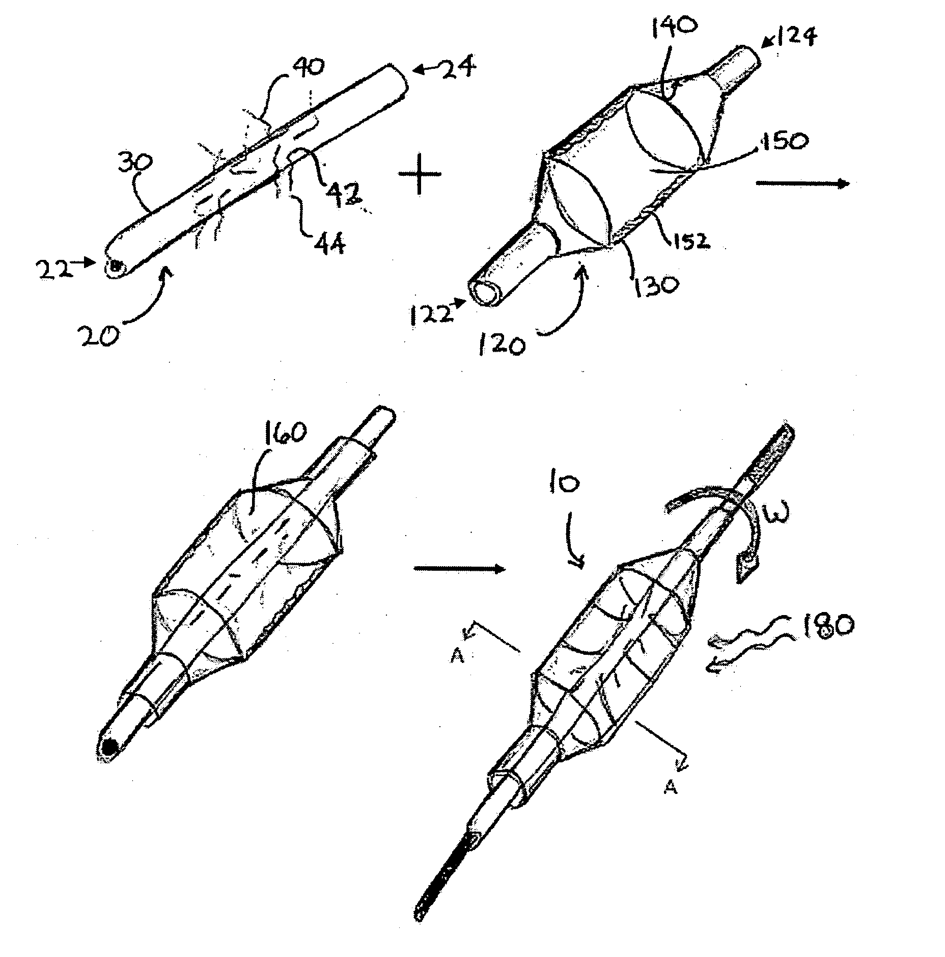
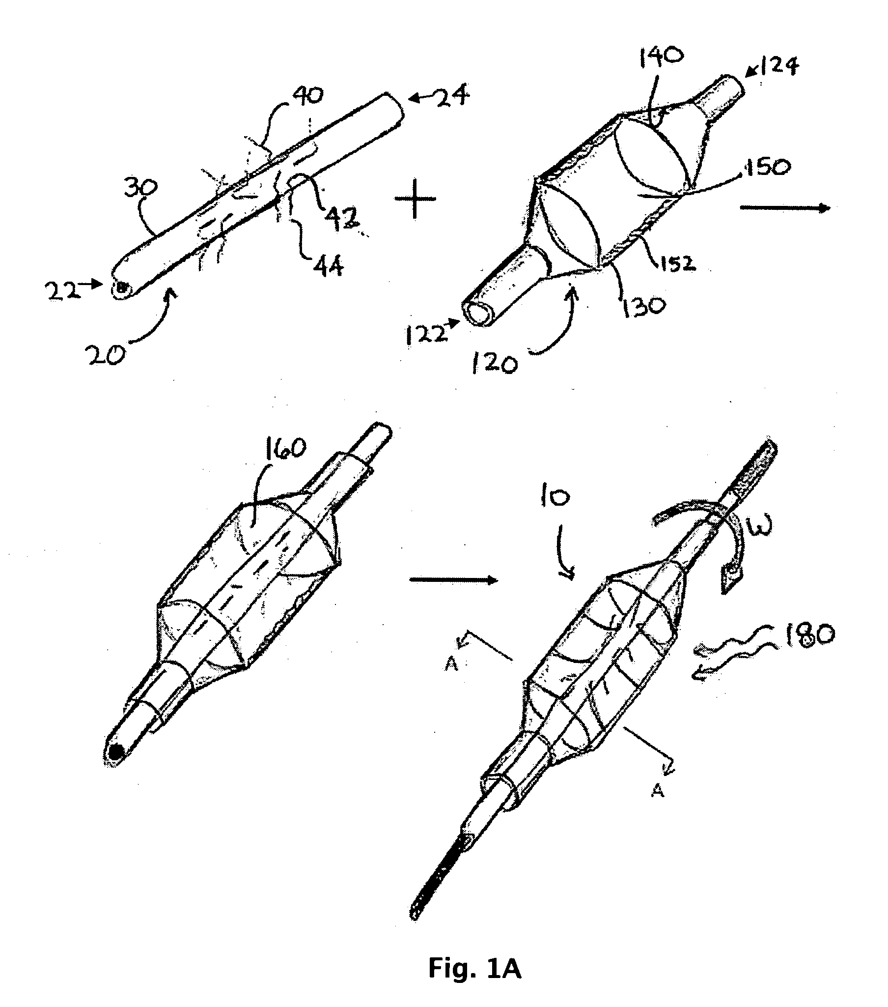
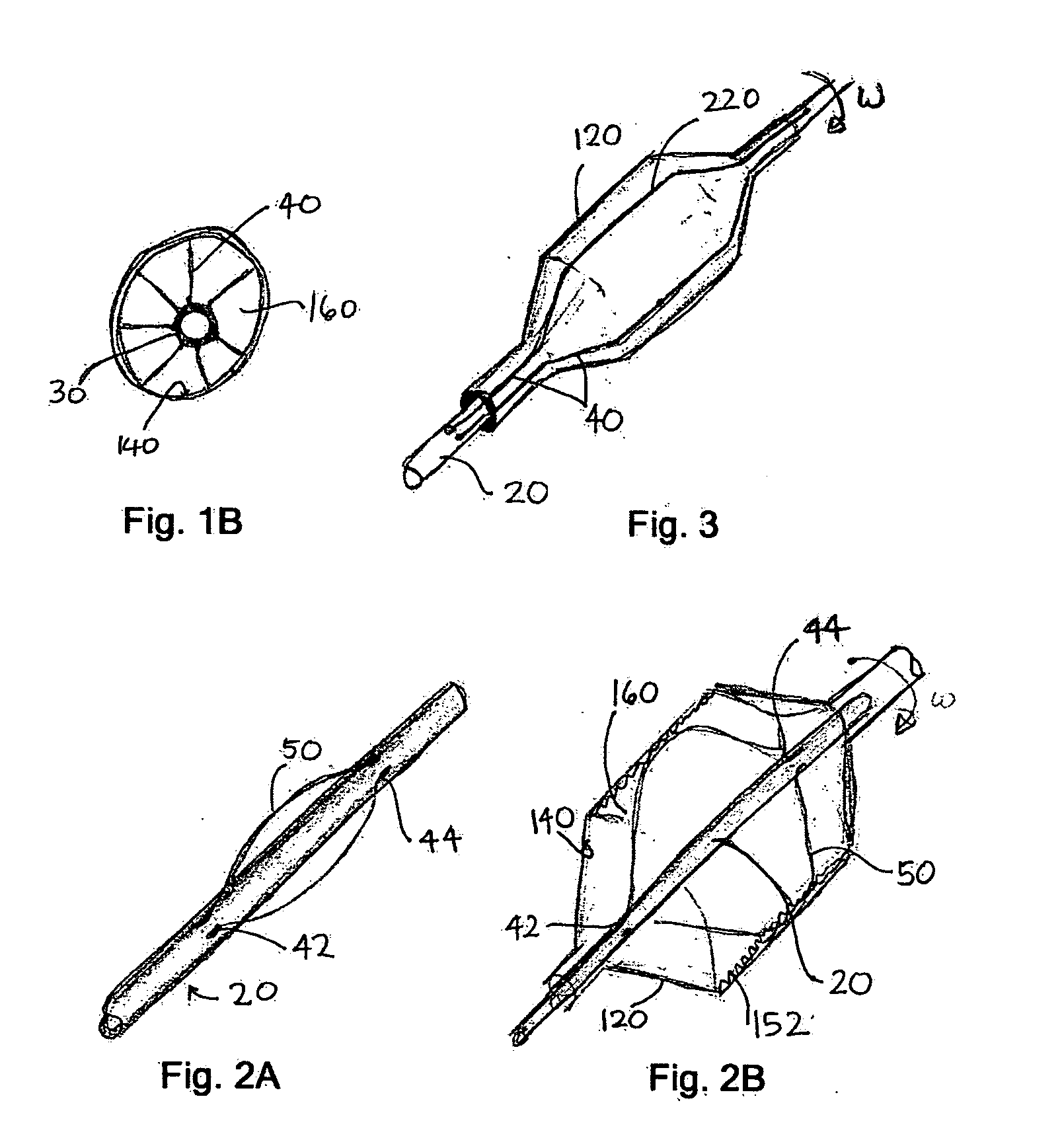
[0032]FIG. 1A illustrates a method producing a reinforced balloon catheter 10, according to one particular embodiment of the present invention. The balloon catheter 10 shown comprises two components, an inflatable balloon 120 and a flexible elongate member 20. The inflatable balloon 120 comprises a proximal end 122 and a distal end 124, as well as an outer surface 130 and an inner surface 140 that defines a volume 150. The flexible elongate member 20 likewise comprises a proximal end 22 and a distal end 24 and is placed within the inner volume 150 of the inflatable...


PUM


Abstract

The present invention generally relates to the field of intravascular medical devices, and more specifically to the field of balloon catheters and other similar diagnostic or therapeutic catheters within the body for treatment and diagnosis of diseases. In particular, the present invention relates to reinforced balloon catheters and drug-eluting balloon catheters and corresponding methods for producing same.

Description

FIELD OF THE PRESENT INVENTION [0001] The present invention generally relates to the field of intravascular medical devices, and more specifically to the field of balloon catheters and other similar diagnostic or therapeutic devices for insertion or implantation within the body for treatment or diagnosis of diseases. BACKGROUND [0002] Balloon catheters are being increasingly used to reach remote locations in the body of a patient. When the target is a soft tissue site, the vascular system in the region often consists of vessels of very small diameter. The vessels are also often convoluted, making many sharp twist and bends. To navigate these small tortuous vessels requires a catheter having a correspondingly small outside diameter. The predominant method for achieving small diameters is to use catheters having very thin walls. However, as the walls of a catheter get thinner, they tend to lose their torsional and longitudinal rigidity. Sufficient torsional rigidity must be maintained...

Claims


Application Information

Patent Timeline
IPC IPC(8): A61M29/00A61F2/958
CPCA61M25/10A61M25/1002A61M25/1029A61M25/1034A61M25/1038A61M2025/0058A61M2025/1031A61M2025/105A61M2025/1084
Inventor HOLMAN, THOMAS J.WEBER, JANSCHEWE, SCOTT
Owner BOSTON SCI SCIMED INC
Learn More