Demodulation of multiple signals

a demodulation and signal technology, applied in the field of demodulation of multiple signals, can solve the problems of inability to introduce band-pass filtering, inability to achieve phase modulation carrier systems, etc., and achieve significant spectral saving advantages and robust performance.

Inactive Publication Date: 2006-04-20
WI LAN INC
View PDF53 Cites 60 Cited by
  • Summary
  • Abstract
  • Description
  • Claims
  • Application Information

AI Technical Summary

Benefits of technology

[0049] Changeable (or variable, or selectable) amounts of cross-correlation between Time Constrained Signal (TCS) response processors and / or combined TCS and Long Response (LR) processor and / or post processor filters of in-phase (I) and quadrature (Q) phase signals of BRA Transceivers, MFS and CS baseband signal processing implementations and architectures for tunable RF frequency embodiments having enhanced spectral efficiency and end-to-end performance are disclosed. These new BRA, MFS and CS classes of FQPSK signal processors, modems and transceivers, with Adaptive Antenna Arrays (AAA) and RF power efficient amplifiers and entire Transceivers, operated in fully saturated or NLA mode, with intentionally Mis-Matched (MM) modulation and demodulation filters, transmit BRA and receive BRA filters / processors, disclosed herein, attain high performance advantages and significant spectral savings.
[0051] These new classes of 2nd generation of FQPSK signal processors, modems and transceivers, with Adaptive Antenna Arrays (AAA) and RF power efficient amplifiers and entire Transceivers, operated in BRA, MFS and CS fully saturated NLA mode, or with LIN mode with intentionally Miss-Matched (MM) transmit BRA and receive BRA filters / processors, disclosed herein, have robust performance and significant spectral saving advantages.

Problems solved by technology

For these reasons such systems are not suitable for BRA, robust BER performance NLA operated RF power efficient systems.
Within the present state of the technology, for numerous BRA Transceiver applications, it is not practical to introduce band-pass filtering after the NLA power efficient Radio Frequency (RF) final amplifier stage.
In conventional BPSK, QPSK, OQPSK or SQPSK, and differentially-encoded phase-shift keying systems variants of these systems, such as DBPSK and DQPSK, as well as in pi / 4-DQPSK and trellis coded QPSK and DQPSK, large envelope fluctuations require linearized (LIN) or highly linear transmitters including frequency up-converters and RF power amplifiers and may require expensive linear receivers having linear Automatic Gain Control (AGC) circuits.
A transmitter NLA reduces the time domain envelope fluctuation of conventional QPSK type of band-limited signals and this reduction of the envelope fluctuation, being a signal distortion, is the cause of spectral restoration or spectral regrowth and the cause of unacceptably high levels of out-of-band spectral energy transmission, also known as out-of-band interference.
Linearized or linear amplifiers are less RF power efficient (during the power “on” state, power efficiency being defined as the transmit RF power divided by DC power), are considerably more expensive and / or having less transmit RF power capability, are larger in size, and are not as readily available as NLA amplifiers.
While these earlier issued patents and publications describe material of a background nature, they do not disclose the original new enhanced performance bit rate agile and modulation agile / selectable technologies disclosed in this new invention.

Method used


Image

  • Demodulation of multiple signals
  • Demodulation of multiple signals
  • Demodulation of multiple signals

Examples


Embodiment Construction

Introductory Description of Embodiments of the Invention

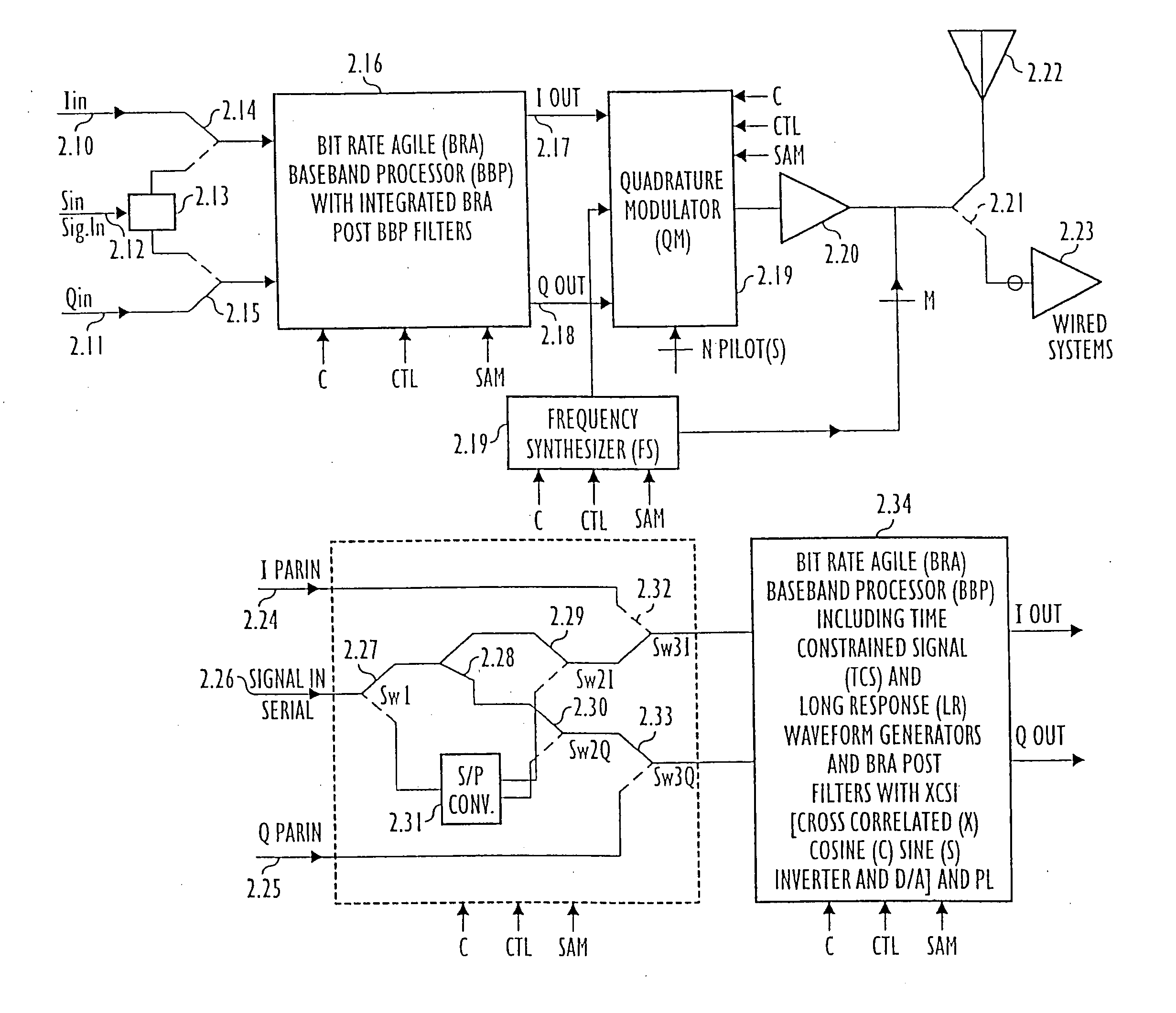
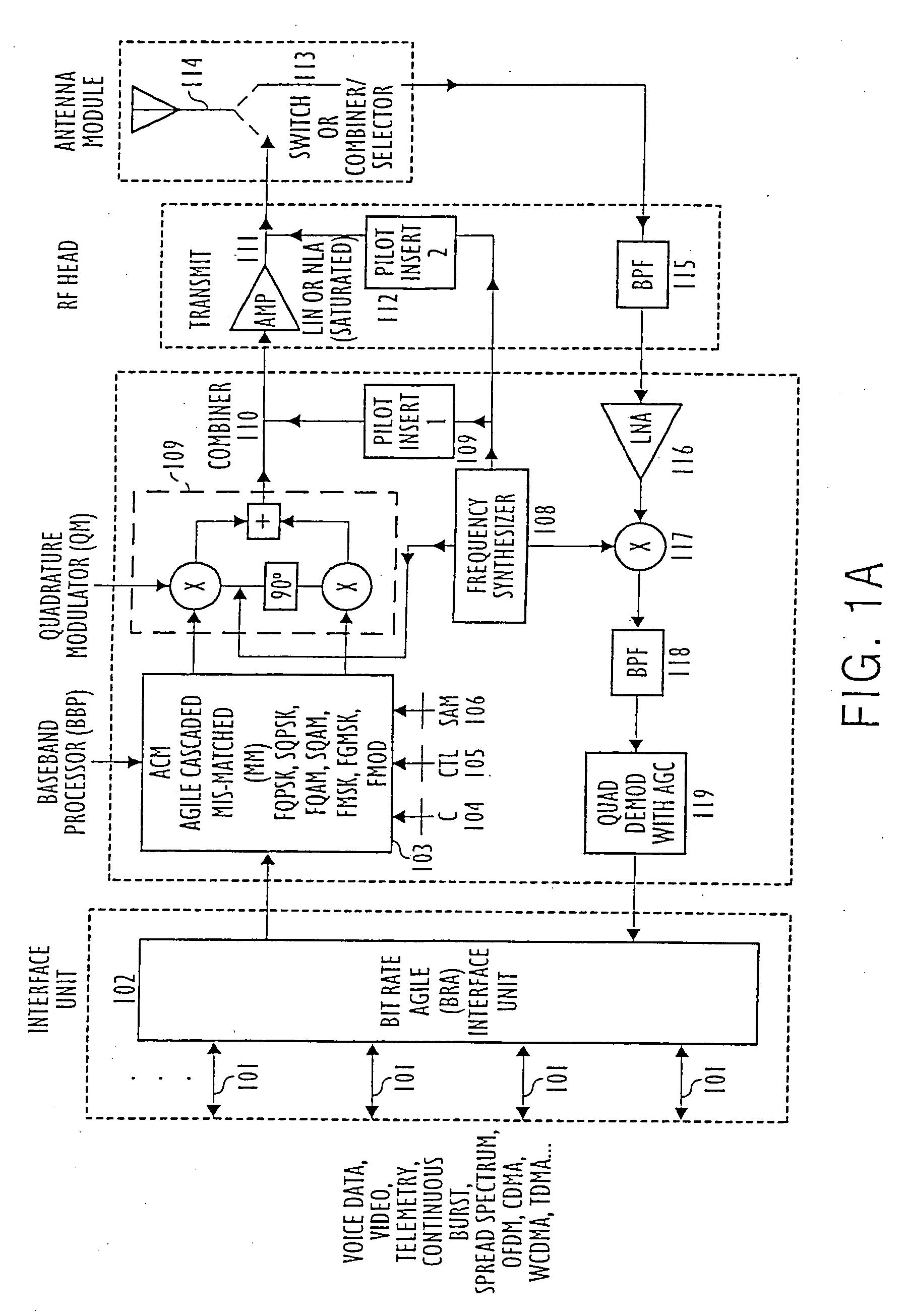
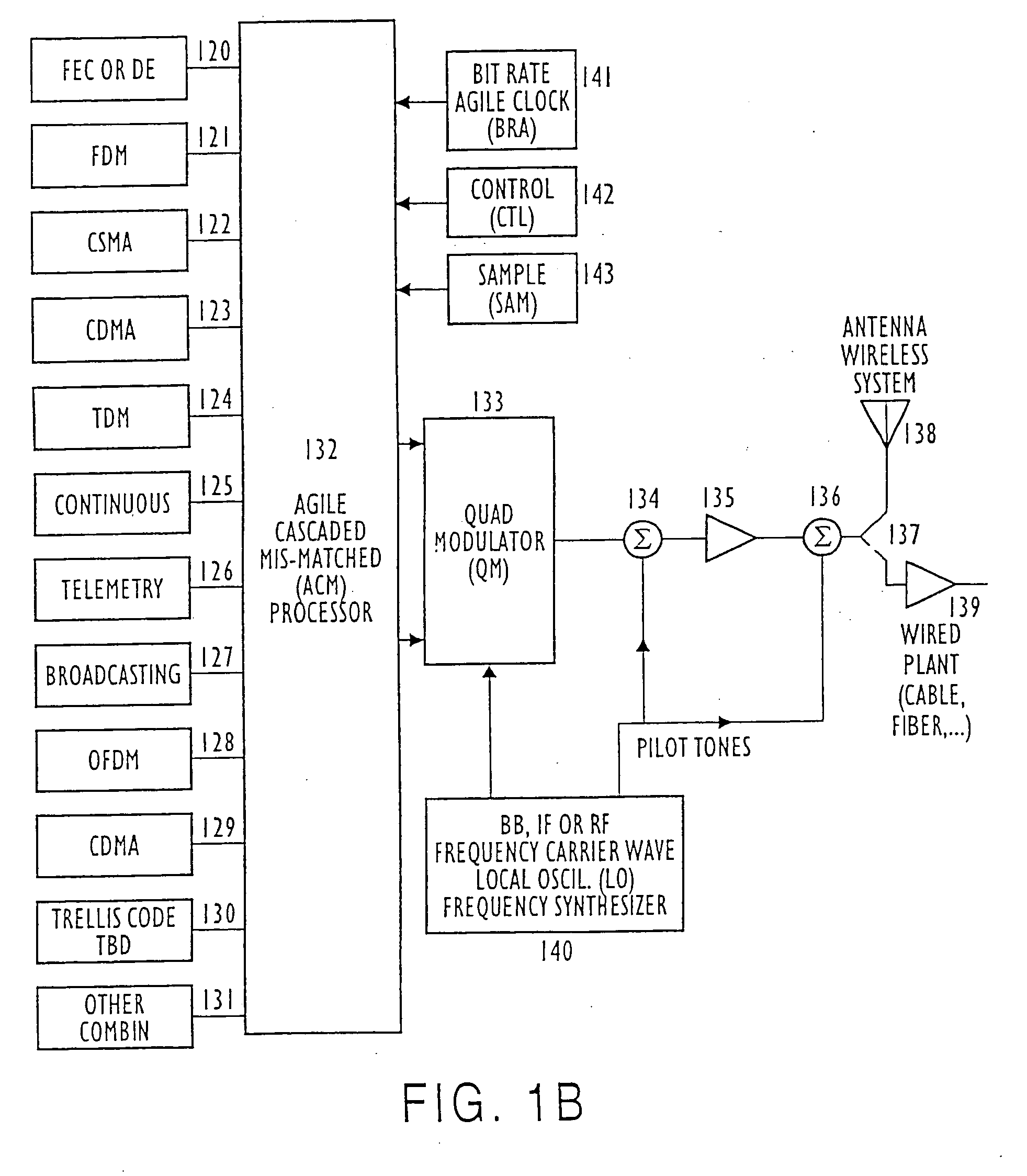
[0100] This invention relates in part to Bit Rate Agile (BRA) signal processors and particularly to cross-correlated (abbreviated “CC” or “Xcor”) and to Agile Cascaded Mis-Matched (ACM) signal processors for increasing the RF spectral efficiency and RF power efficiency of modulated transmitted signals including digital binary, and digital multilevel signals, and of analog modulated signals operated in linearized (LIN) and in power efficient Non-Linearly Amplified (NLA) systems. Cross-correlated quadrature phase, frequency, and amplitude modulated Transmitter and Receiver (Transceiver) systems are described. The use of section headings is for convenience only and is not intended to delimit the discussion of particular aspects of the invention as aspects, features, embodiments, advantages, and applications are described through the specification and drawings. Acronyms are used extensively throughout the description to avoid exce...


PUM


Abstract

A demodulation system for receiving and demodulating multiple modulated signals, including a first modulated signal having a first bit rate and / or a first modulation format and a second modulated signal having a second bit rate and / or a second modulation format. The demodulator demodulating the first modulation format modulated signal provides a cross-correlated demodulated in-phase and quadrature-phase baseband signal and the demodulator demodulating the second modulation format modulated signal provides a second demodulated baseband signal. A selector selects either the first or the second or both bit rate and / or modulation format demodulated baseband signals. In an alternative embodiment two demodulators are implemented for the demodulation of multiple signals. In certain embodiments the demodulator demodulating the first bit rate modulated signal or the second bit rate modulated signal is comprised of bit rate switchable filters and / or mis-matched filters which are mismatched to that of the filters of the modulator of the first or the second bit rate modulated signal. In some of the applications the first or the second modulated signal is an Orthogonal Frequency Division Multiplexed (OFDM) modulated signal and / or a spread spectrum modulated signal and / or Phase Shift Keying (PSK) modulation, or a Quadrature Modulation (QM), or a Frequency Modulation (FM) modulated signal. In certain implementations and applications the demodulator is used for demodulation of Gaussian Minimum Shift Keying (GMSK) modulated signals and spread spectrum modulated signals.

Description

RELATED APPLICATIONS [0001] This Application is a Continuation Application of U.S. patent application Ser. No. 11 / 105,295, filed on Apr. 14, 2005, which is a continuation Application of U.S. patent application Ser. No. 10 / 205,478, filed on Jul. 24, 2002 and of U.S. patent application Ser. No. 09 / 370,360, filed on Aug. 9, 1999, now U.S. Pat. No. 6,470,055 and claims the benefit of the aforementioned applications. Related Applications are also listed in the Attached Supplemental Information Disclosure (SID). [0002] This application claims the benefit under 35 U.S.C. 119(e) of U.S. Provisional Patent Application Ser. No. 60 / 095,943 entitled “FQPSK TRANSCEIVERS” filed 10 Aug. 1998 [PP3]; and incorporated herein by reference. [0003] Other related United States Patent Applications are co-pending U.S. Utility patent application Ser. No. 09 / 111,723 [PP1] filed 8 Jul. 1998 and entitled “FMOD TRANSCEIVERS INCLUDING CONTINUOUS AND BURST OPERATED TDMA, FDMA, SPREAD SPECTRUM CDMA, WCDMA AND CSMA...

Claims


Application Information

Patent Timeline
Patent Type & Authority Applications(United States)
IPC IPC(8): H04L27/00H04B1/707H04L7/00H04L25/03H04L25/49H04L27/18H04L27/26H04L27/34
CPCH04B1/69H04B7/0602H04B7/0854H04B2201/70703H04B2201/70707H04L1/205H04L5/0008H04L5/0016H04L5/0028H04L7/0008H04L25/03025H04L25/0305H04L25/0307H04L25/4902H04L27/00H04L27/0004H04L27/0008H04L27/01H04L27/18H04L27/186H04L27/2017H04L27/2637H04L27/34H04L2025/03407H04L2025/03414H04L2025/03477
Inventor FEHER, KAMILO
Owner WI LAN INC
Why Eureka
Try Eureka