Error correction apparatus and method

a technology of error correction and apparatus, applied in the field of error correction apparatus and method, can solve the problems of varying errors of each individual receiver, and achieve the effect of increasing system speed and conserving bandwidth usag

Inactive Publication Date: 2006-04-20
WEGENER COMM
View PDF89 Cites 50 Cited by
  • Summary
  • Abstract
  • Description
  • Claims
  • Application Information

AI Technical Summary

Benefits of technology

[0019] It is in view of the above problems that the present invention was developed. The present invention is a system, method, apparatus and data structure for correcting errors in the transmission of content data files over distribution networks. A compressed memory is used to identify portions of transmitted content data files where transmission errors have occurred. The compressed memory, which may be in the form of a bitmap for example, is returned to a transmission uplink controller via a low bandwidth back channel, for example the Internet. The information in the compressed, transmitted memory is used by the uplink control system of the transmitter to re-transmit those portions of previously transmitted content data files that were not properly received due to error. Re-transmitting content data files originally received with errors insures the proper delivery of error free audio, video or data files. By re-transmitting only the portions, or packets, of the transmitted content data files that contain errors, system speed is increased and bandwidth usage is conserved.
[0022] The control processor for the uplink also aggregates the bitmaps for the various individual receivers. Each individual receiver may have varying errors due to local conditions such as rain, damage to equipment or power loss. The system of the present invention conserves bandwidth usage and promotes speed by initiating error correction only upon a signal from the transmitter, as opposed to receiving error messages from multiple servers in a piecemeal or repeating fashion initiated by the receivers. Speed is further promoted and bandwidth usage conserved by aggregating the required re-transmissions for all of the receivers into a single or minimal number of transmissions. Continuous loops are avoided by ending the re-transmission after a designated number of re-transmission attempts have been completed.

Problems solved by technology

Each individual receiver may have varying errors due to local conditions such as rain, damage to equipment or power loss.

Method used


Image

  • Error correction apparatus and method
  • Error correction apparatus and method
  • Error correction apparatus and method

Examples


example

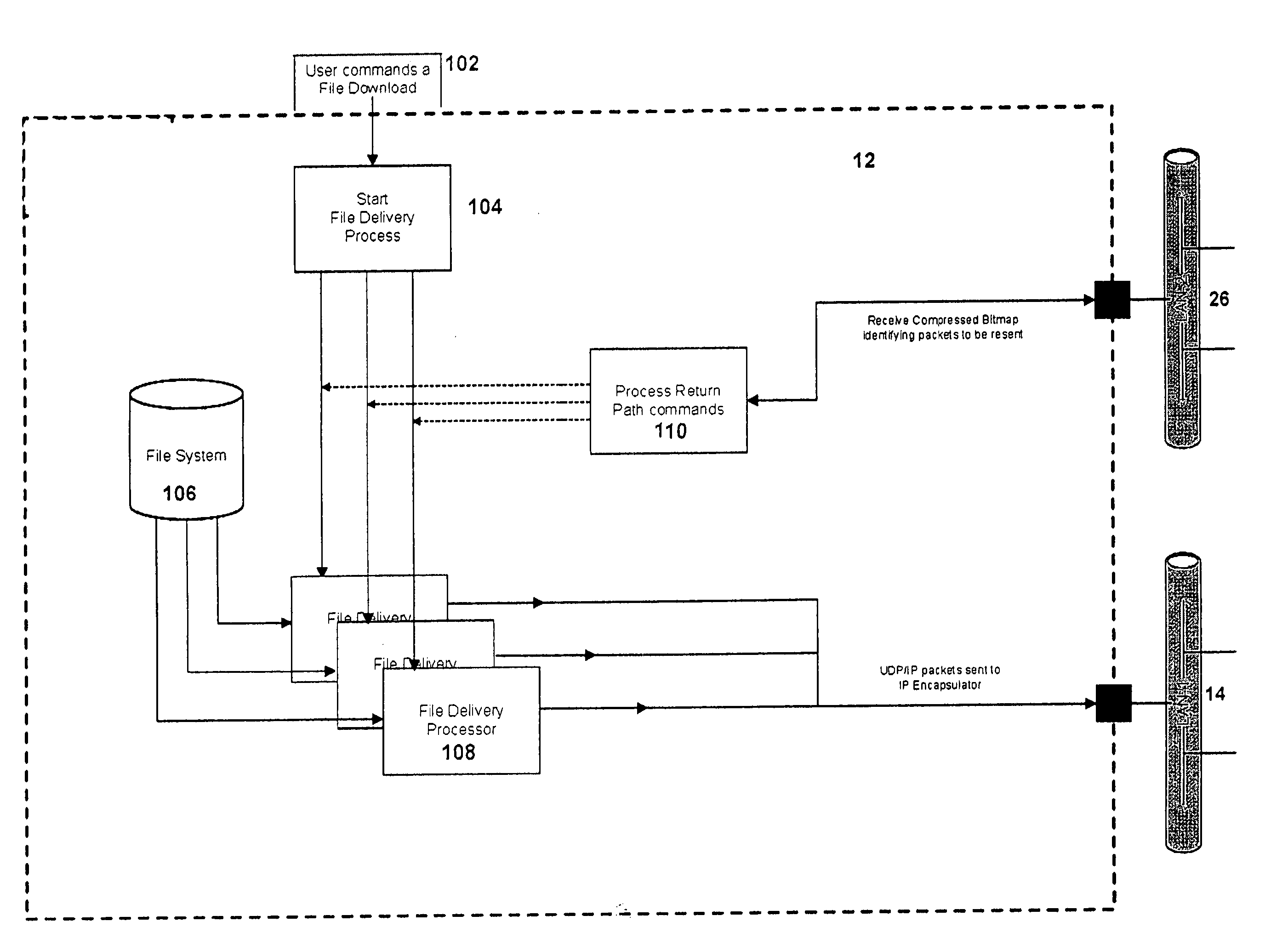
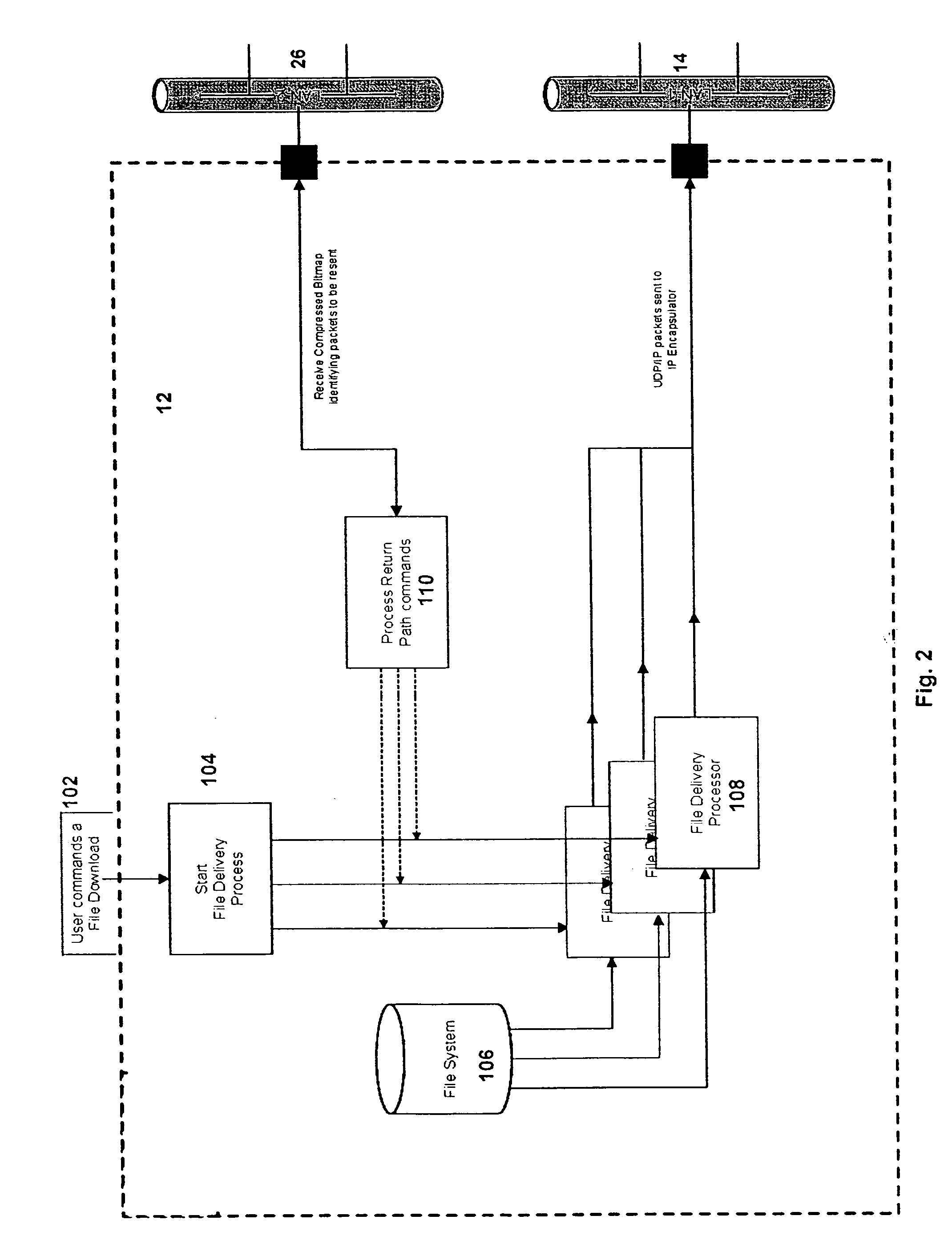
[0077] By way of example, if the content data file to be transmitted includes 100 packets (or “blocks”), when the uplink controller receives a command to transmit that file, it will configure and store a bitmap 100 bits long. Each bit will correspond to one of the packets to be transmitted. The bitmap will be further configured of 13 bytes. When the uplink sends the command to initialize and prepare for transmission, it will include an instruction to a receiver control processor to also generate a bitmap that is the same size. Each receiver will create and configure a bitmap that is 100 bits long, in 13 bytes. The last byte will have only 4 bits. Accordingly, both receiver and uplink transmitter will contain the following bitmap: 00000000 00000000 00000000 00000000 00000000 00000000 00000000 00000000 00000000 00000000 00000000 00000000 0000.

[0078] If errors occur in the receipt of particular blocks, the corresponding bits will be turned on (or off) and the transmission proceeds. As...


PUM


Abstract

A system, method and data structure for error correction for use in the transmission of content data distribution networks uses a compressed memory, for example a bitmap, to identify portions of transmitted content data files where transmission errors have occurred. The error memory, is used to generate an error status report that is returned to a transmission controller via a low bandwidth back channel, for example the Internet. The information in multiple error status reports is aggregated by the control system of the transmitter and used to re-transmit those portions of previously transmitted content data files that were not properly received due to error. By re-transmitting only the data packets of the transmitted content data files that contain errors, overall transmission speed is increased and bandwidth usage is conserved.

Description

CROSS-REFERENCE TO RELATED APPLICATIONS [0001] This application is a continuation of U.S. patent application Ser. No. 10 / 448,710 filed on May 30, 2003.BACKGROUND OF THE INVENTION [0002] 1. Field of the Invention [0003] This invention is in the field of broadcast data networks, systems for receiving broadcast data [0004] 2. Related Art [0005] Error correction is an important component of any system for the distribution of content data such as music or video. Error correction is particularly important for systems distributing by satellite or terrestrial broadcast. The increased likelihood of transmission error due to factors such as the atmospheric conditions or damage to receiving equipment increases the importance of insuring complete transmission of content data. [0006] Due to the large amount of data that needs to be transmitted for the distribution of content data such as video, audio and data, there is a continuing need in the art for an efficient use of bandwidth. Content data ...

Claims


Application Information

Patent Timeline
Patent Type & Authority Applications(United States)
IPC IPC(8): H03M13/00G06FH04L1/16
CPCH04L1/1614
Inventor MERRITT, DAVID
Owner WEGENER COMM
Why Eureka
Try Eureka