LED endoscope illuminator and methods of mounting within an endoscope

a technology of led endoscope and endoscope, which is applied in the field of led endoscope illuminator and mounting methods within the endoscope, can solve the problems of poor coupling of light emitted by the led(s) into the optical fiber, large amount of heat, and inefficient conversion of electrical power to light, and achieves the effects of high efficiency, small size and high power

Active Publication Date: 2006-04-27
OPTIM
View PDF24 Cites 54 Cited by
  • Summary
  • Abstract
  • Description
  • Claims
  • Application Information

AI Technical Summary

Benefits of technology

[0006] Recent advances in light emitting diodes (LEDs) have seen the advent of very high power LEDs, up to 5 W. This invention utilizes a high power white light LED as a light source for medical and industrial endoscopes. The high power, very small size, and high efficiency of these devices makes it possible to design an untethered endoscope; an endoscope without a light guide umbilical connecting the endoscope to an external light source. As a result, in some embodiments, the invention is directed to an endoscope with a light source mounted within a handle of the endoscope. In certain embodiments, a battery to power the light source is also positioned in the handle so that the endoscope is untethered. An advantage of this embodiment is that a user has full range of motion without being tied to an external power source. In addition, another advantage is that the endoscope is light in weight.
[0007] In general, the invention relates to an endoscope with a battery powered, high power LED incorporated into the endoscope handle. By close coupling of a light guide bundle to the LED without the use of additional optical components, a large amount of the light emitted by the LED can be coupled directly into the fibers of the light guide bundle. As a result, a greater amount of light from the LED can be transmitted to the distal end of the endoscope which illuminates objects under investigation. Embodiments of the present invention do not include auxiliary optics, such as lenses or mirrors, disposed between the light source and the light guide bundle, but instead rely on the small size of the LED's emitting region and the close placement (e.g., direct contact or close proximity) of the light guide bundle to the emitting region. Because the LED itself is very efficient in converting electrical energy into light and the described optical interface is very efficient at coupling this light from the LED into the light guide fiber, this new light source can be powered by small batteries that will operate for a considerable length of time without the need for battery replacement or recharging, and without making the endoscope handle cumbersome or unwieldy. The lack of auxiliary optics between the light source and the light guide bundle simplifies the mechanical design and volume of space within the handle needed for the light source. The high light output and high coupling efficiency of the light emitted by the LED into the light guide fiber increases battery lifetime and / or permits the use of smaller capacity, and smaller volume batteries.

Problems solved by technology

Both types of lamps, filament and arc, are very inefficient in converting electrical power to light, and consequently produce large amounts of heat.
Multiple LEDs are necessary because the light output from a single, low power LED is very low and there is poor coupling of light emitted by the LED(s) into the optical fiber.
This type of arrangement would be difficult if not impossible to implement with a high power LED because of the high operating temperature of these LEDs (up to 135 degrees C).
At high temperatures, the epoxy used in typical LED packages will melt or crack due to thermal cycling.
In addition, high temperatures will cause the epoxy to discolor, typically becoming yellow.
This will impart a yellow cast to the light, thereby lowering its effective color temperature and its desirability as a visual light source.

Method used


Image

  • LED endoscope illuminator and methods of mounting within an endoscope
  • LED endoscope illuminator and methods of mounting within an endoscope
  • LED endoscope illuminator and methods of mounting within an endoscope

Examples


Embodiment Construction

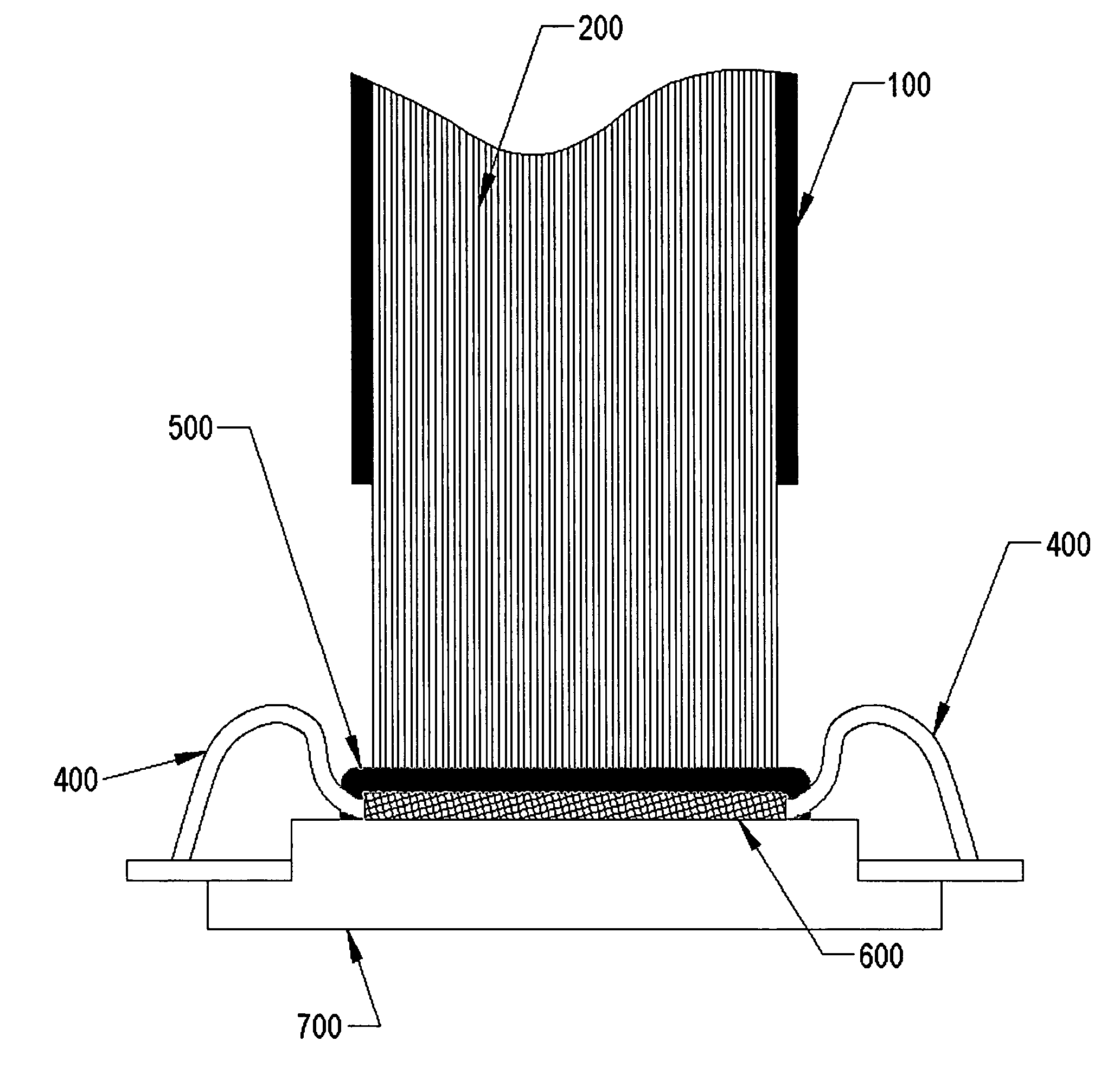
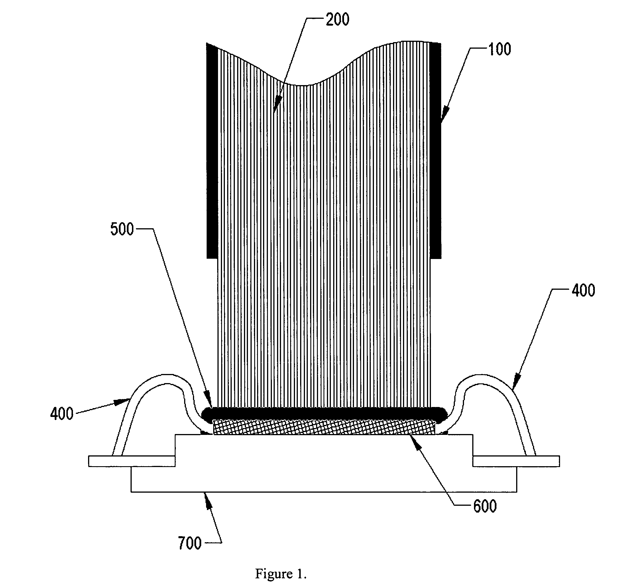
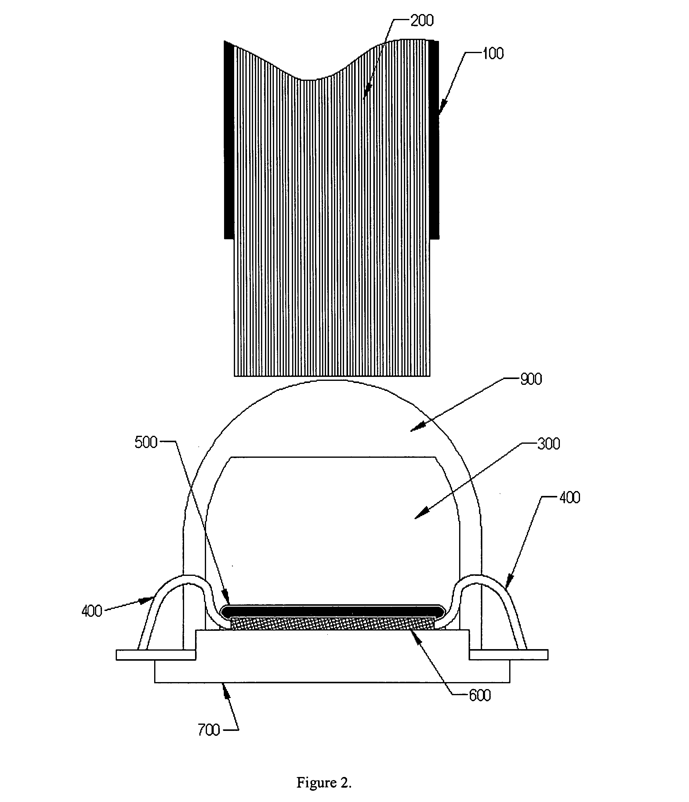
[0019] One embodiment of this invention utilizes a high power LED (Luxeon III Model LXHL-LW3C, Lumileds Lighting, LLC, 370 W, Trimble Road, San Jose, Calif. 95131) with a typical forward voltage of 3.7V and operating current at 700 mA. This device can be safely operated up to a current of 1A with a corresponding typical forward voltage of 3.9V. This white LED has a typical color temperature of 5500K. The LED chip has an emitting surface of approximately 1 mm=1 mm, and is coated with a wavelength conversion phosphor (and / or fluorophor) that emits a broadband continuum of visible white light between about 470-700 nm.

[0020] The light emitting area of the LED is coupled to a small 1 mm square or round bundle of light guide fibers; a typical light guide bundle size used in endoscopes. The light guide bundle is composed of hundreds of individual glass (or plastic) fibers grouped together to form a single bundle at the light source, and either a single bundle or multiple bundles at the di...


PUM

PropertyMeasurementUnit
color temperatureaaaaaaaaaa
electrical power consumptionaaaaaaaaaa

Abstract

The present invention is directed to methods of mounting a light source, such as, for example a high-efficiency, high-power solid state light source (e.g., a LED) within a handle of an endoscope. One of the methods of the present invention includes removing a portion of a package surrounding the light source to expose a light source chip, positioning the exposed light source adjacent to a chassis within the handle and in contact with an end of a light guide bundle, translating the light source with the exposed light source chip about the end of the light guide while measuring light output from an illumination (i.e., distal) end of the light guide bundle with a photodetector, and securing the exposed light source to the chassis at a position in which maximum light output is measured.

Description

CROSS REFERENCE TO RELATED APPLICATION [0001] This application claims the benefit of the filing date of U.S. Provisional Patent Application Ser. No. 60 / 611,006, filed on Sep. 17, 2004, the entirety of which is incorporated herein by reference.FIELD OF THE INVENTION [0002] This invention relates to a remote illumination device using a high-power LED and a fiber optic light guide. BACKGROUND OF THE INVENTION [0003] Light sources for endoscopic use are generally of two types: incandescent filament lamps and arc lamps. Incandescent lamps produce light by passing current through a tungsten filament, causing it to radiate light in proportion to its blackbody color temperature. The hotter the filament, the higher its color temperature and the more nearly it approaches daylight with a color temperature of approximately 5500K. Tungsten filament lamps range in color temperature from approximately 2400-3400K. Because of the low color temperature, objects illuminated by a tungsten filament ligh...

Claims


Application Information

Patent Timeline
Patent Type & Authority Applications(United States)
IPC IPC(8): H01P11/00
CPCA61B1/0011A61B1/07Y10T29/49016A61B1/0684A61B1/00032
Inventor BENNETT, HUDSON D.KRUPA, ROBERT J.LAFLASH, WILLIAM F.MAHER, MATTHEW G.ROOT, THOMAS V.
Owner OPTIM
Why Eureka
Try Eureka