Holographic filter with a wide angular field of view and a narrow spectral bandwidth

Inactive Publication Date: 2006-05-04
POSTECH CO LTD
View PDF16 Cites 5 Cited by
  • Summary
  • Abstract
  • Description
  • Claims
  • Application Information

AI Technical Summary

Benefits of technology

[0013] Among other advantages, the optical filter of the present invention provides a narrow spectral bandpass filter that accepts light over an wide angular field of view without significantly reducing the signal to noise ratio. Holograms particularly useful for this application are made from photopolymerizable materials, but can also be made from photorefractive materials, photochromic materials and the like. Photopolymer holograms can be made into a variety of shapes, sizes and thickness consistent with the requirements of this application. They generally exhibit the dynamic range needed for hologram multiplexing, and furthermore the resulting holograms are environmentally stable.

Problems solved by technology

Two related problems can limit the direct use of a single narrow-spectral-bandwidth, reflection hologram to select the desired signal beam.
Further, increasing the thickness of a reflection hologram, or, for example, the optical pathlength of a waveguide, narrows the spectral bandwidth but also reduces the angular field of view.

Method used


Image

  • Holographic filter with a wide angular field of view and a narrow spectral bandwidth
  • Holographic filter with a wide angular field of view and a narrow spectral bandwidth
  • Holographic filter with a wide angular field of view and a narrow spectral bandwidth

Examples


Embodiment Construction

[0020] A description of preferred embodiments of the invention follows.

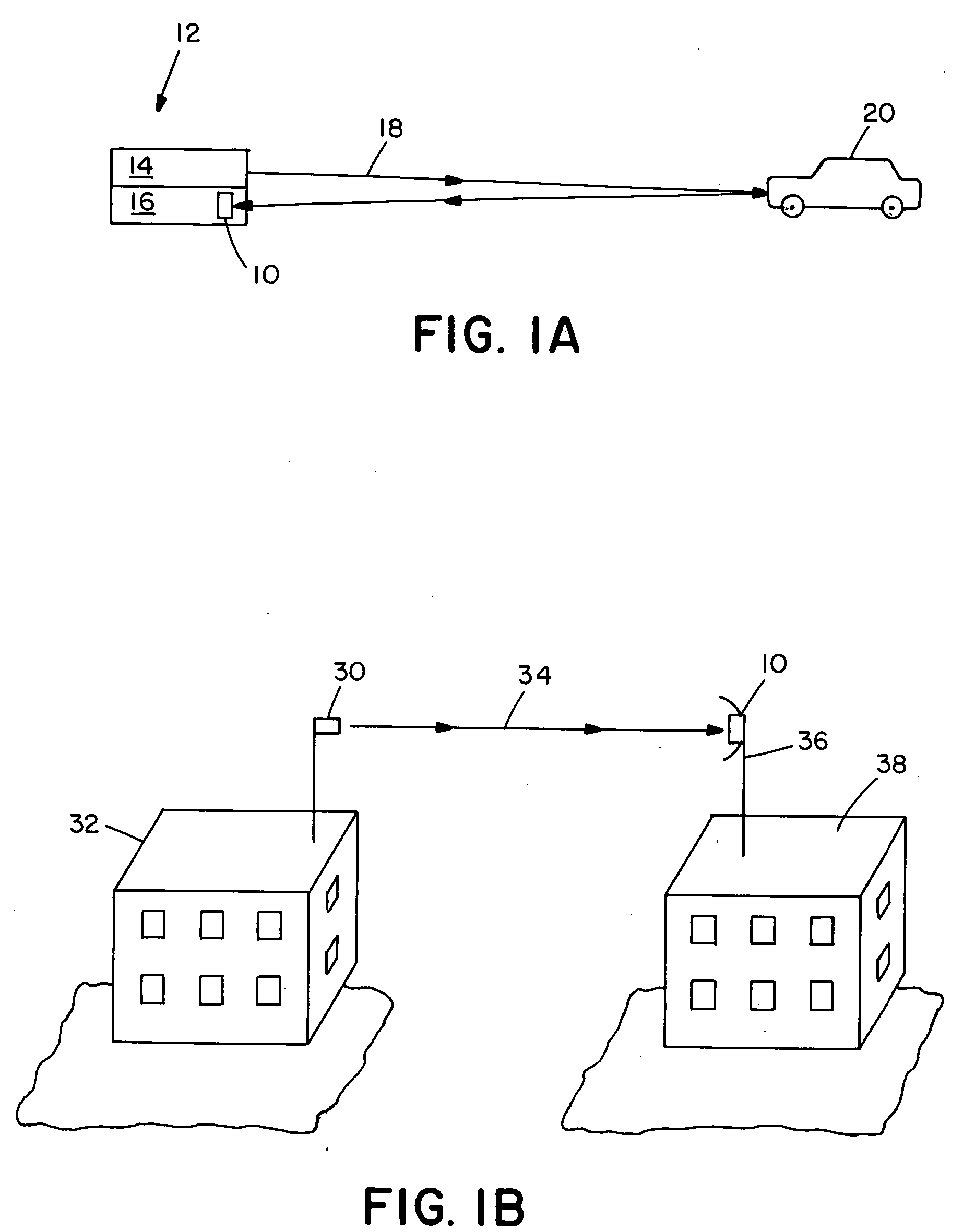
[0021] There are shown in FIGS. 1A and 1B implementations of a holographic filter 10 in accordance with the present invention. In FIG. 1A, a light detection and ranging system (LIDAR) system 12 includes a laser source 14 and a detector or receiver 16 provided with the holographic filter 10. The laser source 14 directs a light beam 18 at an object 20, such as an automobile, airplane, or submarine, which reflects the beam back to the detector 16. In a LIDAR system used as a range finder, electronics within the LIDAR measures the time interval between when the source 14 emits the light beam 18 and the detector senses the reflected beam from the object 20. The distance between the LIDAR system 12 is then easily calculated from the product of the measured time interval and the speed of light.

[0022] In FIG. 1B, a “last milefiber optics network uses an optical transmitter 30 located on top of a building 32 that send...


PUM


Abstract

A holographic optical filter that includes an optical recording medium for storing several multiplexed reflection holograms that are formed by successive interference between two or more collimated object beams with a common collimated reference beam. The object beams are incident to the recording material at a series of angles chosen to provide reflection efficiency over the desired filed of view at the specified wavelength.

Description

RELATED APPLICATIONS [0001] This application is a continuation of U.S. application Ser. No. 10 / 170,007, filed Jun. 11, 2002, which claims the benefit of U.S. Provisional Application No. 60 / 297,307, filed Jun. 11, 2001, the entire contents of which are incorporated herein by reference.BACKGROUND OF THE INVENTION [0002] Bragg gratings are structures with a periodic variation in the refractive index that are usually formed in optical components such as holograms, waveguides, and optical fibers. These structures reflect a narrow spectral and angular bandwidth of light that is determined by the average refractive index of the grating, and the spatial period of the refractive index variation. [0003] The fraction of incident light that is reflected by Bragg gratings is determined by the magnitude of the refractive index variation and by the number of refractive index periods included in the structure. Reflectivity greater than 99% can be obtained in Bragg structures that have only 100 μm t...

Claims


Application Information

Patent Timeline
IPC IPC(8): G02B5/32G01S7/481G03H1/26
CPCG01S7/4816G02B5/203G02B5/32G03H1/26
Inventor INGWALL, RICHARD T.WALDMAN, DAVID A.
Owner POSTECH CO LTD
Why Eureka
Try Eureka