

High-power amplified spectrally combined mode-locked laser
- Summary
- Abstract
- Description
- Claims
- Application Information
AI Technical Summary
Benefits of technology
Problems solved by technology
Method used
Image

Examples
Embodiment Construction
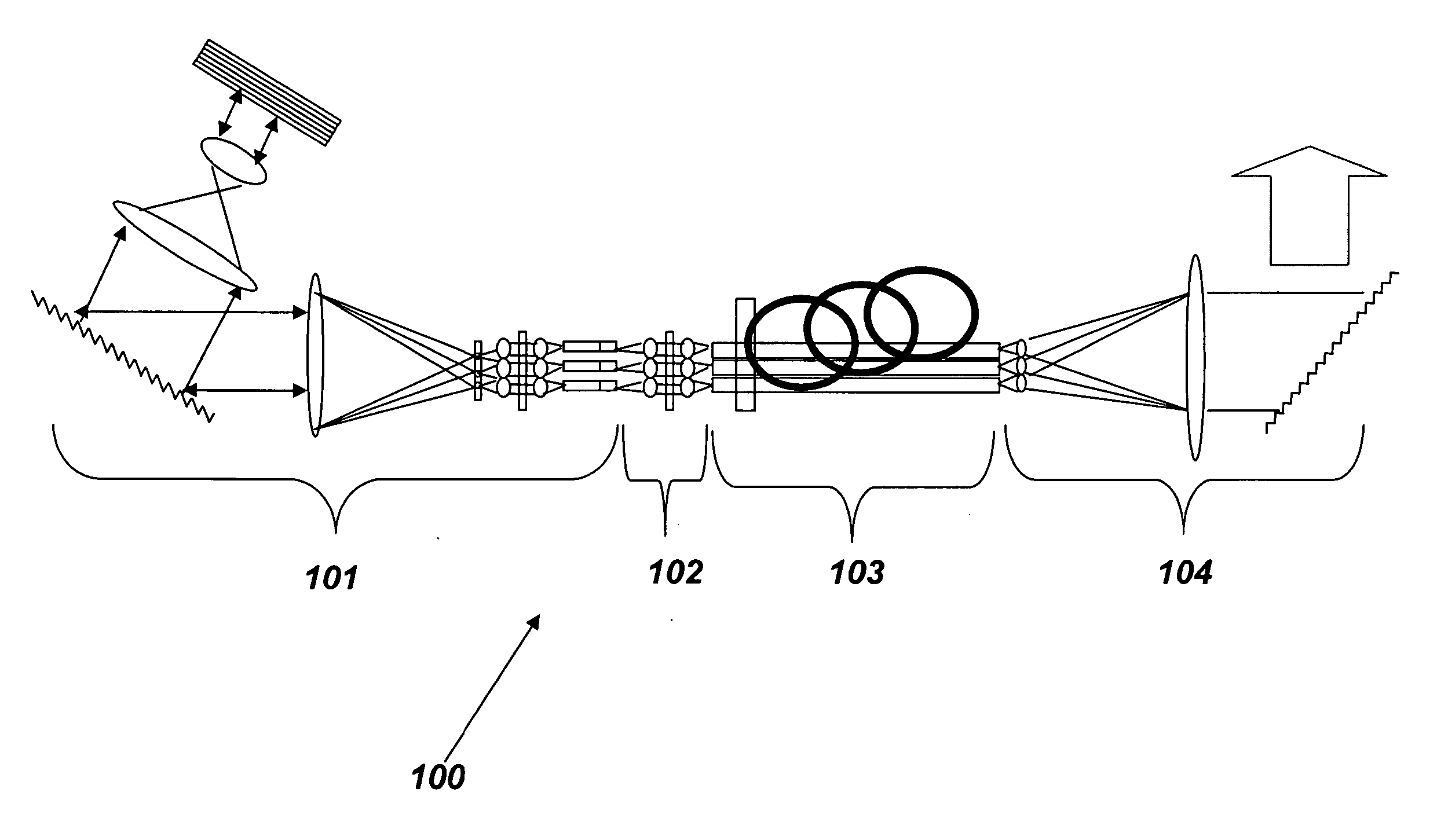
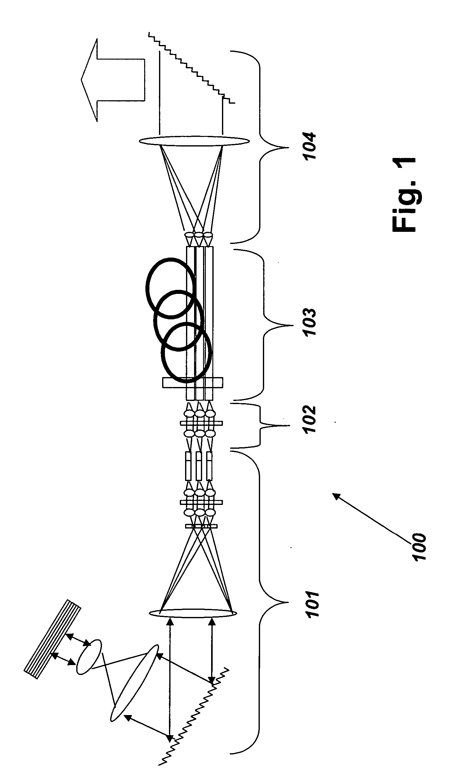
[0022] The system described herein is directed to a laser system with a plurality of gain elements, such as optical fibers, laser crystals, e.g. microlasers, and semiconductor lasers that are mode-locked in common in an external cavity. The system is also directed to an amplified laser system wherein the output of each gain element is directed to a separate fiber amplifier section, with the output beams from the amplifier section spectrally combined into a common amplified overlapping output beam.
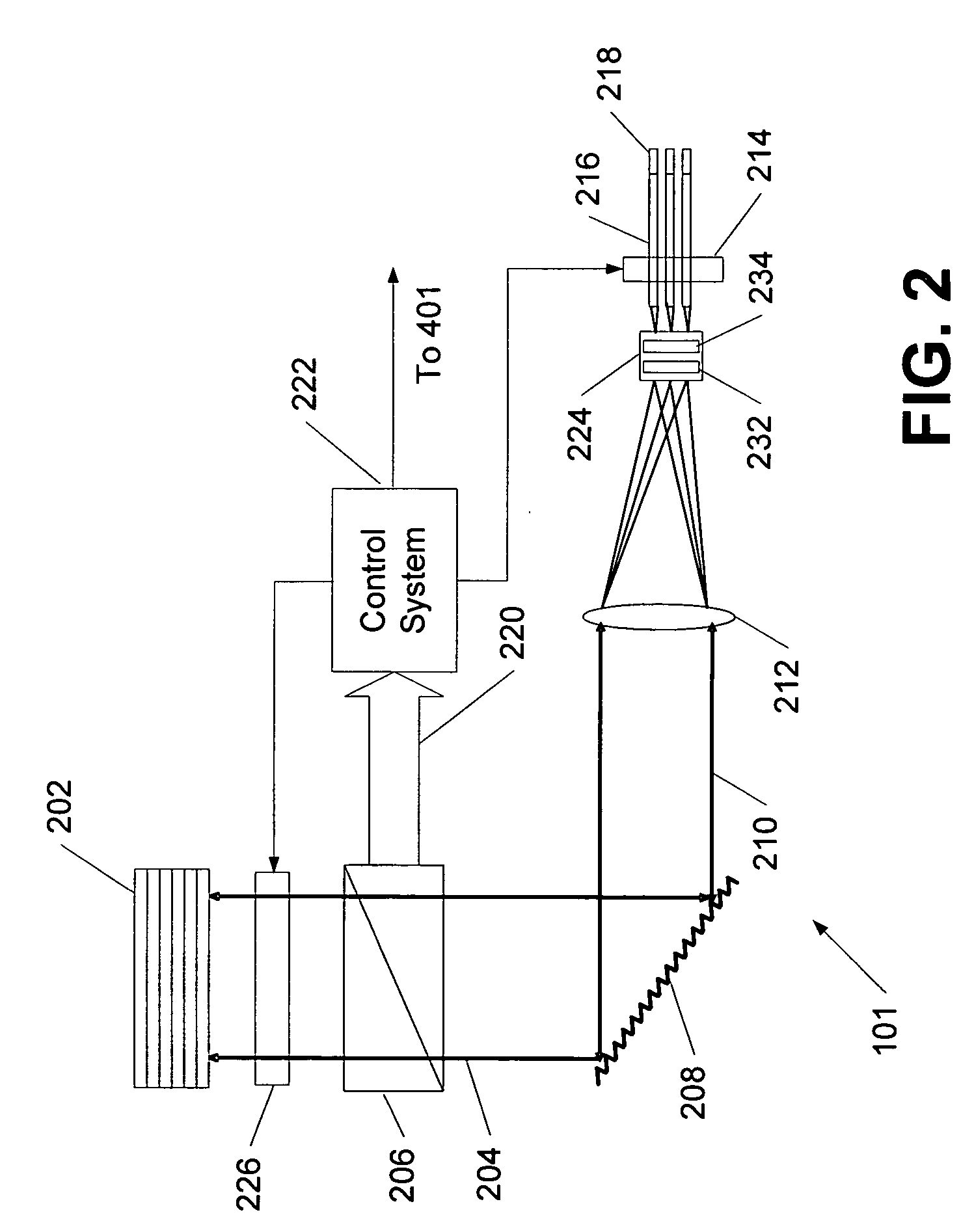
[0023]FIG. 1 shows schematically an amplified laser system 100 with an oscillator section 101 with a plurality of separate gain elements that generate commonly mode-locked and / or Q-switched laser beams, and an amplifier section 103 with a plurality of amplifying fibers that receive the laser beams from the oscillator section 101 and produce amplified laser beams, which are then collimated and combined by beam combiner section 104 into a common overlapping amplified output beam. The oscilla...
PUM
 Abstract
Description
Claims
Application Information