Device for heat-treating a coating of flat-bed offset printing plates

a technology of offset printing plate and coating, which is applied in the direction of lighting and heating equipment, furnace components, furnace types, etc., can solve the problems of increasing the tendency of exposure or non-exposure flatbed, hindering the operation of mounting the printing plate, and increasing the temperature of the printing plate, so as to reduce the tendency of exposure and non-exposure flatbed, and maintain the effect of downtime as short as possibl

Inactive Publication Date: 2006-05-11
TECHNO GRAFICA
View PDF19 Cites 6 Cited by
  • Summary
  • Abstract
  • Description
  • Claims
  • Application Information

AI Technical Summary

Benefits of technology

[0010] Modern rotary offset presses are extremely expensive so that everything is done to keep downtimes as short as possible. If possible, the presses should be kept running in three-shift operation without interruption. It is, therefore, of great interest to prevent, if possible, any unevenness in flat-bed offset printing plates.
[0011] Now, it is the object of the present invention to open up a way for achieving coatings that are hardened more uniformly, and flat-bed offset printing plates that are less uneven.
[0012] This object is achieved by a device having the features defined in claim 1. Advantageous further developments of the invention are the subject-matter of the sub-claims.
[0013] The device according to the invention comprises an upper hot-air chamber and a lower hot-air chamber arranged at a distance below the upper hot-air chamber. Arranged in the space between the two hot-air chambers is the carrying run of an air-permeable endless conveyer belt, which extends between the two hot-air chambers and serves to convey the flat-bed offset printing plates through the space between the two hot-air chambers. Except for an entry opening and an exit opening for the carrying run of the conveyer belt, the space between the two hot-air chambers is closed toward the outside. A first air diffuser is provided on the bottom of the upper hot-air chamber. A second air diffuser is provided on the top of the lower hot-air chamber. The two air diffusers are provided with a plurality of air outlet openings that face the conveyer belt and at least one inlet opening which is connected with the intake side of one or more blowers. The invention provides substantial advantages:
[0014] By having the hot air act on both sides, the printing plate is heated up more rapidly and more uniformly.
[0015] The air diffusers, associated to the upper hot-air chamber and the lower hot-air chamber, are designed to distribute the air through their air outlet openings in such a way that uniform heating-up of the printing plate is achieved.

Problems solved by technology

Heat-treating exposed or non-exposed flat-bed offset printing plates is connected with two significant problems:
On the other hand, it has been found that as a result of the heat-treating process flat-bed offset printing plates tend to become uneven, which tendency becomes the more pronounced as the size and thickness of the flat-bed offset printing plates decrease.
Such unevenness hinders the operation of mounting the printing plate on the printing cylinder.
The flat-bed offset printing plate can be straightened, and its unevenness can be largely corrected, during the process of mounting it on a printing cylinder, but this is a difficult operation.
Especially disadvantageous effects are produced by such unevenness on modern rotary offset presses which are equipped with automatic infeed means for the flat-bed offset printing plates.
However, an uneven flat-bed offset printing plate lends itself to automatic feeding either not at all or only with difficulty.
In case of trouble, it is practically impossible to intervene manually in a rotary offset press with automatic infeed unit.
In case the flat-bed offset printing plate gets stuck during the infeed process, before it is correctly mounted, the printing plate or, even worse, the press roller may be destroyed.
Modern rotary offset presses are extremely expensive so that everything is done to keep downtimes as short as possible.

Method used


Image

  • Device for heat-treating a coating of flat-bed offset printing plates
  • Device for heat-treating a coating of flat-bed offset printing plates
  • Device for heat-treating a coating of flat-bed offset printing plates

Examples


Embodiment Construction

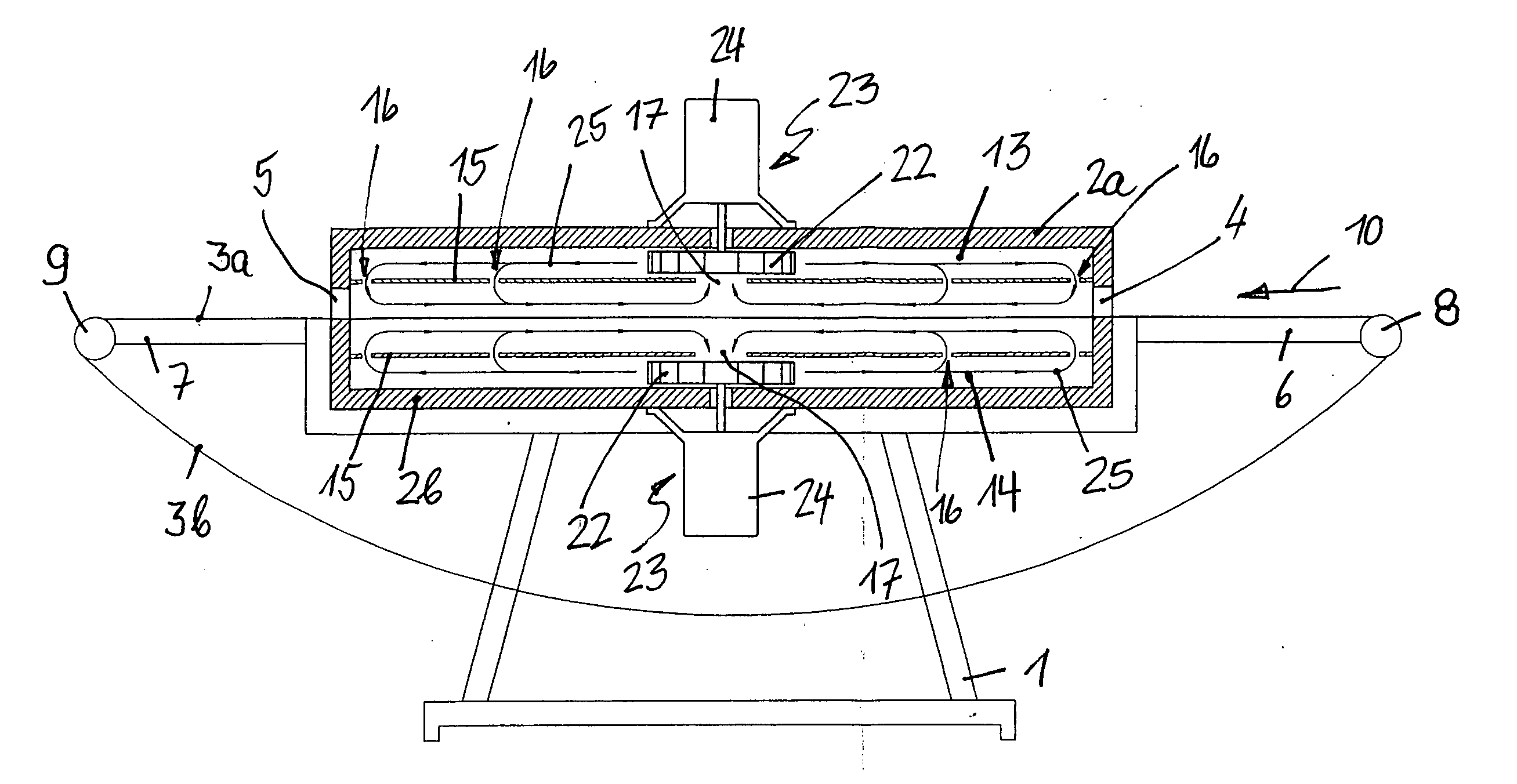
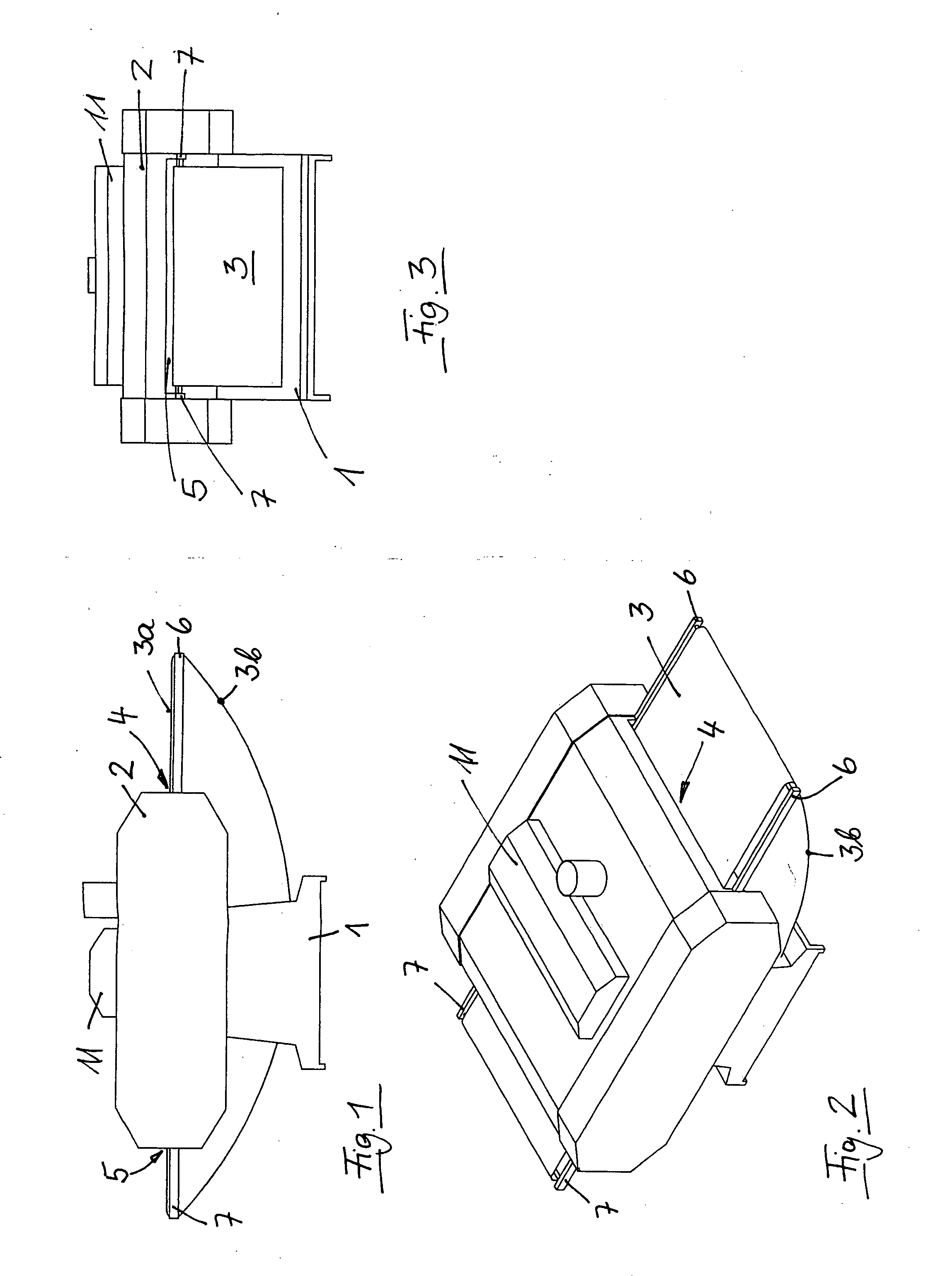
[0036] The device, which is shown from the outside in FIGS. 1 to 3, comprises a housing 2, arranged on a frame 1, which is passed by an endless conveyer belt 3. The housing is provided with a horizontal slot-shaped entry opening 4, through which a conveyer belt 3 enters, and a horizontal slot-like exit opening 5 through which the conveyer belt 3 leaves the housing. Two arms 6, carrying a free-running guide roller 8, are attached in front of the entry opening 4. Two arms 7, carrying a driven guide roller 9, are attached in front of the exit opening 5, for drawing the carrying run 3a of the conveyer belt 3 through the housing 2 in tight condition, whereas the lower run 3b is guided back to the guide roller 8 in sagged condition.

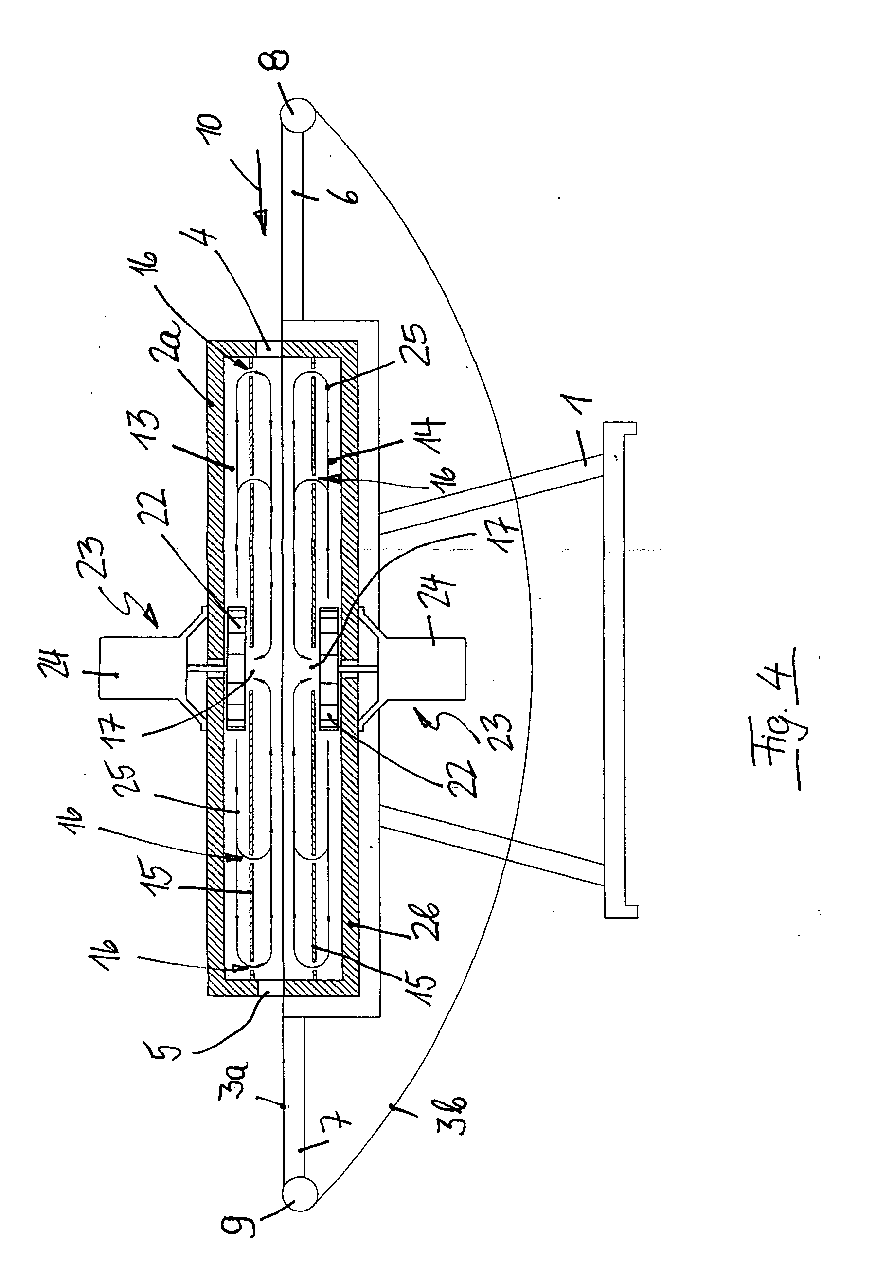
[0037] The drive motors 24 of two blowers 12 are located below a hood 11 on the housing 2, see FIG. 4. The drive motors of two additional blowers, not shown in FIGS. 1 to 3, are located at the bottom of the housing 2.

[0038] The housing 2 comprises an upper ho...


PUM

PropertyMeasurementUnit
thickaaaaaaaaaa
temperatureaaaaaaaaaa
distanceaaaaaaaaaa

Abstract

The present invention provides a device for heat-treating a coating of flat-bed offset printing plates by application of hot air upon the flat-bed offset printing plates, comprises an upper hot-air chamber: a lower hot-air chamber, arranged at a distance from the upper hot-air chamber below the latter; an air-permeable endless conveyer belt having a carrying run, which extends between the upper and the lower hot-air chambers; a first air diffuser provided on the bottom of the upper hot-air chamber, and a second air diffuser provided on the top of the lower hot-air chamber. The two air diffusers are provided with air outlet openings that face the conveyer belt and at least one air inlet opening which is connected with the intake side of one or more blowers. The space between the two hot-air chambers, except for an entry opening for the carrying run and an exit opening for the carrying run for the conveyer belt, is closed.

Description

BACKGROUND OF THE INVENTION [0001] 1. Field of the Invention [0002] The present invention relates to a device for heat-treating the exposed or non-exposed coating of flat-bed offset printing plates in a continuous process. [0003] 2. Description of Related Art [0004] Flat-bed offset printing plates comprise a light-sensitive coating, based for example on a diazo layer, which is structured according to the image to be printed by an exposure process. The coating is carried on a metal plate, typically 0.15 mm to 0.5 mm thick, which in most cases consists of aluminum, in rare cases also of another metal or a metal alloy, for example a hard copper-chromium alloy. Once exposed, the flat-bed offset printing plate is developed by a wet-chemical process, is washed, dried and heat-treated to increase the hardness of the developed coating. The heat-treating process is also described as heat-fusing process and may be carried out also prior to the exposing operation. [0005] The service life of a ...

Claims


Application Information

Patent Timeline
Patent Type & Authority Applications(United States)
IPC IPC(8): B41F23/04B41C1/10B41N3/00F27B9/06F27B9/10F27B9/20F27B9/24F27B9/36F27D7/04G03F7/26
CPCB41C1/10B41N3/00F27B9/063F27B9/10F27B9/20F27B9/243F27B9/36F27D7/04G03F7/26
Inventor HANOSEK, PETER
Owner TECHNO GRAFICA
Why Eureka
Try Eureka