Method of producing an image on a printing screen

a printing screen and image technology, applied in the field of computer to screen (cts) imaging system, can solve the problems of reducing the exposure rate of both methods, and re-deposition of debris, so as to achieve rapid and economical production of high-resolution stencils, improve image definition, and improve the effect of image definition

Inactive Publication Date: 2006-05-11
NAT RES COUNCIL OF CANADA +2
View PDF3 Cites 18 Cited by
  • Summary
  • Abstract
  • Description
  • Claims
  • Application Information

AI Technical Summary

Benefits of technology

[0019] The present invention seeks to provide a method and apparatus that will reduce the tendency for an inkjet applied curing agent to spread beyond the point of initial contact and thus improve image definition. It is also within the scope of this invention to show how additional solids can be incorporated within the body of the emulsion as it cures using this method and apparatus. It is the further purpose of this invention to show how to use optical curing and chemical curing in combination to rapidly and economically produce a high resolution stencil. It is also a purpose of this invention to provide a method and apparatus to deposit an emulsion with an inkjet. The invention, further seeks to provide a method and apparatus that will incorporate a solid into the body of an emulsion as it cures. It is a further purpose of this invention to provide a method and apparatus that can deposit a self-curing emulsion that manufacturers its own solids within its body.
[0021] Accordingly, the present invention provides a simple and efficient method of generating a stencil using a computer to screen imaging system.

Problems solved by technology

Each one of these known methods has a number of serious limitations.
For example, debris re-deposition is an issue with the laser ablation and like the laser direct image method it is a point by point process.
This limits the exposure rate of both methods.
Mechanical instability and reliability will be inherent issues with the MEMS method.
This represents an added complexity.
However the chemical as used plays no role in the crosslinkng process nor does it improve the image resolution.
These requirements are contrary to the properties of an ink.
Therefore the art that is taught in U.S. Pat. No. 5,380,769 is not applicable to a screen emulsion.
Although CA 02088400, EP-A-0492351, U.S. Pat. No. 5,380,769, EP 0909642 in combination teaches the general art of producing a stencil from a digital file but the stencils produced by these methods are generally unsatisfactory.
There are many factors that make producing a stencil by this known art challenging.
The phase change as described in U.S. Pat. No. 5,380,769 can only be used to control the resolution of the image but it does not improve the durability of the ink.

Method used


Image

  • Method of producing an image on a printing screen
  • Method of producing an image on a printing screen

Examples


Embodiment Construction

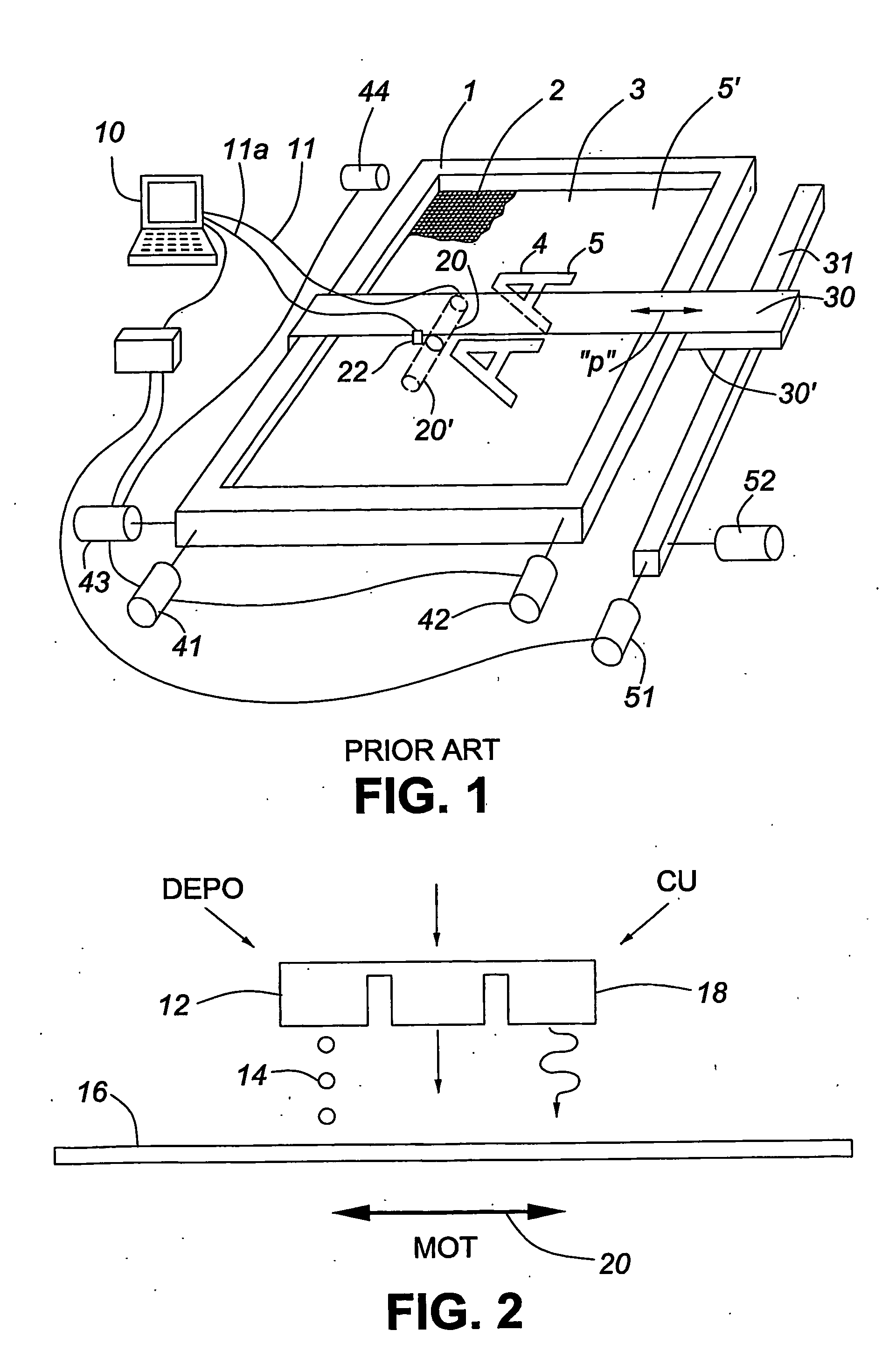
[0029]FIG. 1 illustrates a prior art method as described in aforementioned U.S. Pat. No. 5,875,712 in which an inkjet printer is used to deposit light blocking material onto an emulsion coated screen where the material prevents light from reaching the screen so that the unexposed emulsion underneath the blocking material can be washed away.

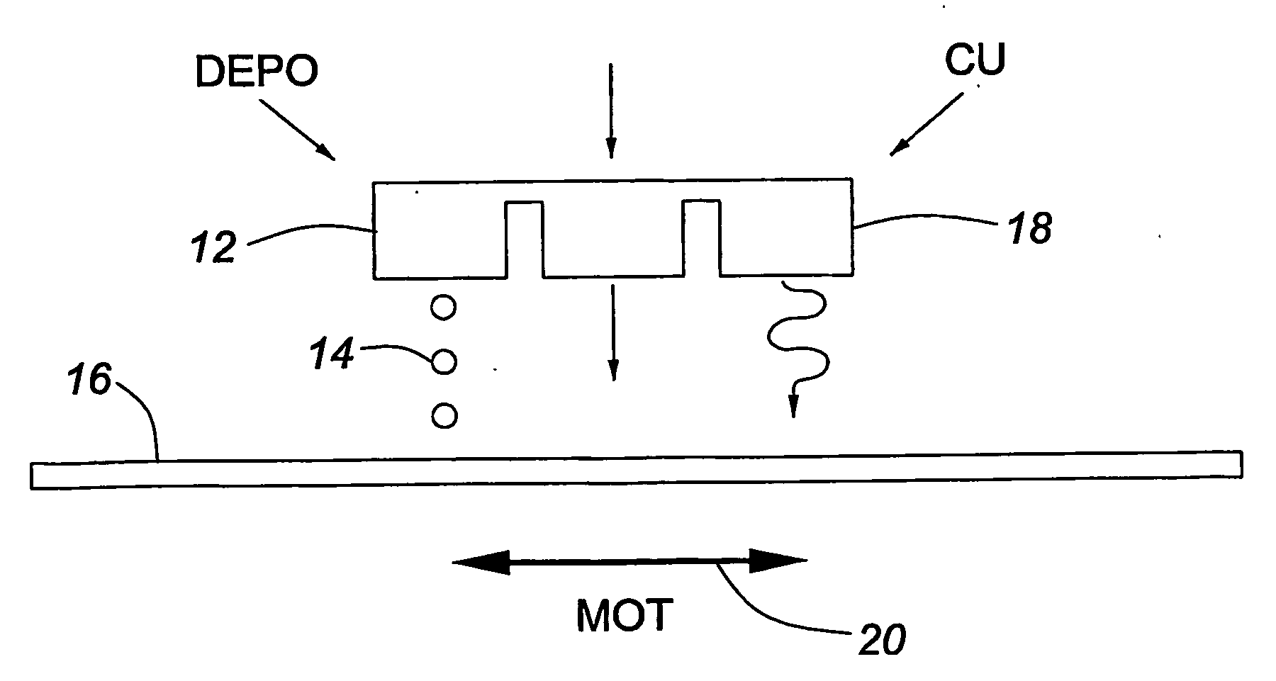
[0030] The present invention makes use of inlet printing technology in a computer to screen (CTS) imaging system. It is well known that digital imaging techniques can be used to store, in a computer, digital images of patterns which are to be reproduced on a silk screen or a lithography plate for generating a screen or plate. The concept is analogous to the production of a printed image on a sheet of paper wherein “ink” is ejected onto the paper as a reproduction of the image stored in the computer. In the present invention this technology is extended to depositing patterns onto a silk screen or lithographic plate using various techniques. In one...


PUM

PropertyMeasurementUnit
sizeaaaaaaaaaa
particle sizeaaaaaaaaaa
particulate sizesaaaaaaaaaa

Abstract

Methods of producing an image on a printing screen are described. The method uses inkjet printing technology to form an image on the screen using a computer to screen or computer to plate imaging technique. According to particular embodiments a specially formulated emulsion is used in which the emulsion is mixed with a cross-linking agent to create a self curing image.

Description

[0001] This application claims benefit of U.S. Provisional Application No. 60 / 422,175 filed Oct. 30, 2002.FIELD OF THE INVENTION [0002] This invention relates to a computer-to-screen (CTS) imaging system and more particularly to systems and methods for reproducing a digitized image on a silk screen stencil or lithography plate. BACKGROUND [0003] In certain printing processes, such as screen printing, a stencil containing, for example, a negative of a desired image is required. In the printing process this stencil is placed on the surface of the carrier to which the image is to be transferred and ink is imprinted through the stencil. [0004] There are numerous existing techniques for preparing the stencil with one of the most common involving the use of a photographically prepared negative which is placed over a screen onto which has been applied a photo activatable emulsion. Such emulsions are typically sensitive to ultraviolet radiation and in this process the screen is exposed to u...

Claims


Application Information

Patent Timeline
Patent Type & Authority Applications(United States)
IPC IPC(8): B41C1/04B41C1/14B41N1/24
CPCB41C1/147B41M5/0011B41M5/0017B41M7/0072B41N1/24
Inventor BOURNE, ORSON L.INGOLD, KEITHKENNEDY, DAVIDWAREBERG, GUNNAR P.GIRARD, DAVIDBAXTER, GARYBAXTER, BRIAN
Owner NAT RES COUNCIL OF CANADA
Why Eureka
Try Eureka