
Catadioptric projection system, and exposure apparatus having the same

Inactive Publication Date: 2006-05-11
CANON KK
View PDF9 Cites 27 Cited by
  • Summary
  • Abstract
  • Description
  • Claims
  • Application Information

AI Technical Summary

Benefits of technology

[0009] The present invention is directed to a catadioptric projection system and an exposure apparatus that shortens a distance between a first object (such as a reticle) and a second object (such as a wafer), and provides excellent imaging performance.

Problems solved by technology

However, these materials do not have a great difference of dispersion, and it is very difficult to correct the chromatic aberration of the optical system having a very high NA like an immersion optical system.
In addition, as the NA becomes higher, an aperture of the glass material becomes large, increasing the cost of the apparatus.
In particular, the NA greater than about 1.1 causes a long distance between an object (or reticle) and an image (or wafer) and a large effective diameter of the glass material, and the large size of the optical system and the high cost of the apparatus are inevitable.
Therefore, the interference among the reticle surface, the reticle stage, the lens and the plane mirror becomes problematic, and it is difficult to maintain a sufficient space.
Therefore, this optical system is unsuitable for the immersion exposure apparatus since the reticle is not parallel to the wafer, and it is difficult to retain the fluid.
As a result, the incident angle range and the maximum incident angle upon the plane mirror increase, and pose a serious problem to the higher NA than 1.
In other word, the higher NA than 1 excessively increases the incident angle range and the maximum incident angle upon the plane mirror, deteriorating the imaging performance due to the aggravated film characteristic of the plane mirror.

Method used


Image

  • Catadioptric projection system, and exposure apparatus having the same
  • Catadioptric projection system, and exposure apparatus having the same
  • Catadioptric projection system, and exposure apparatus having the same

Examples


first embodiment

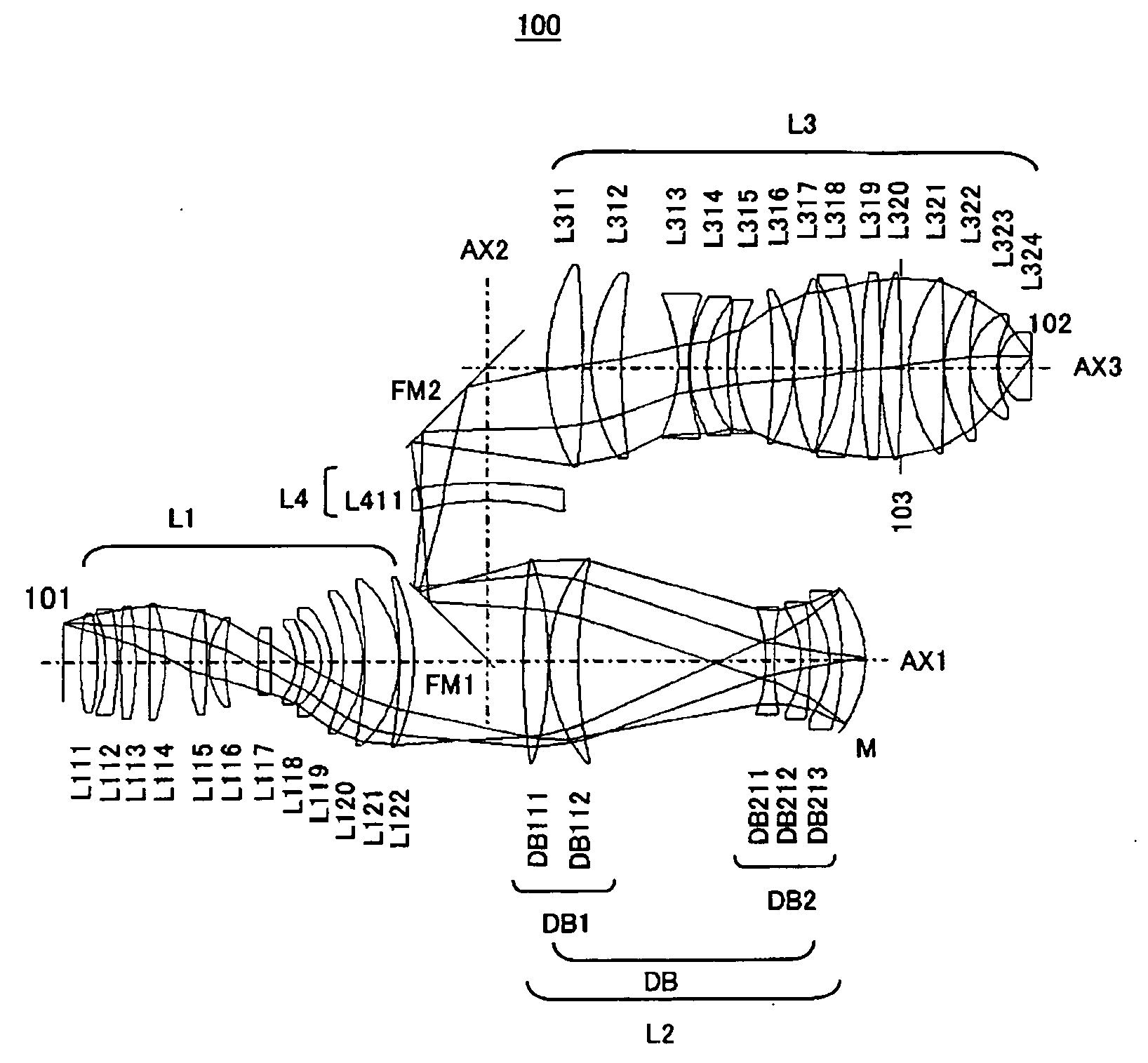
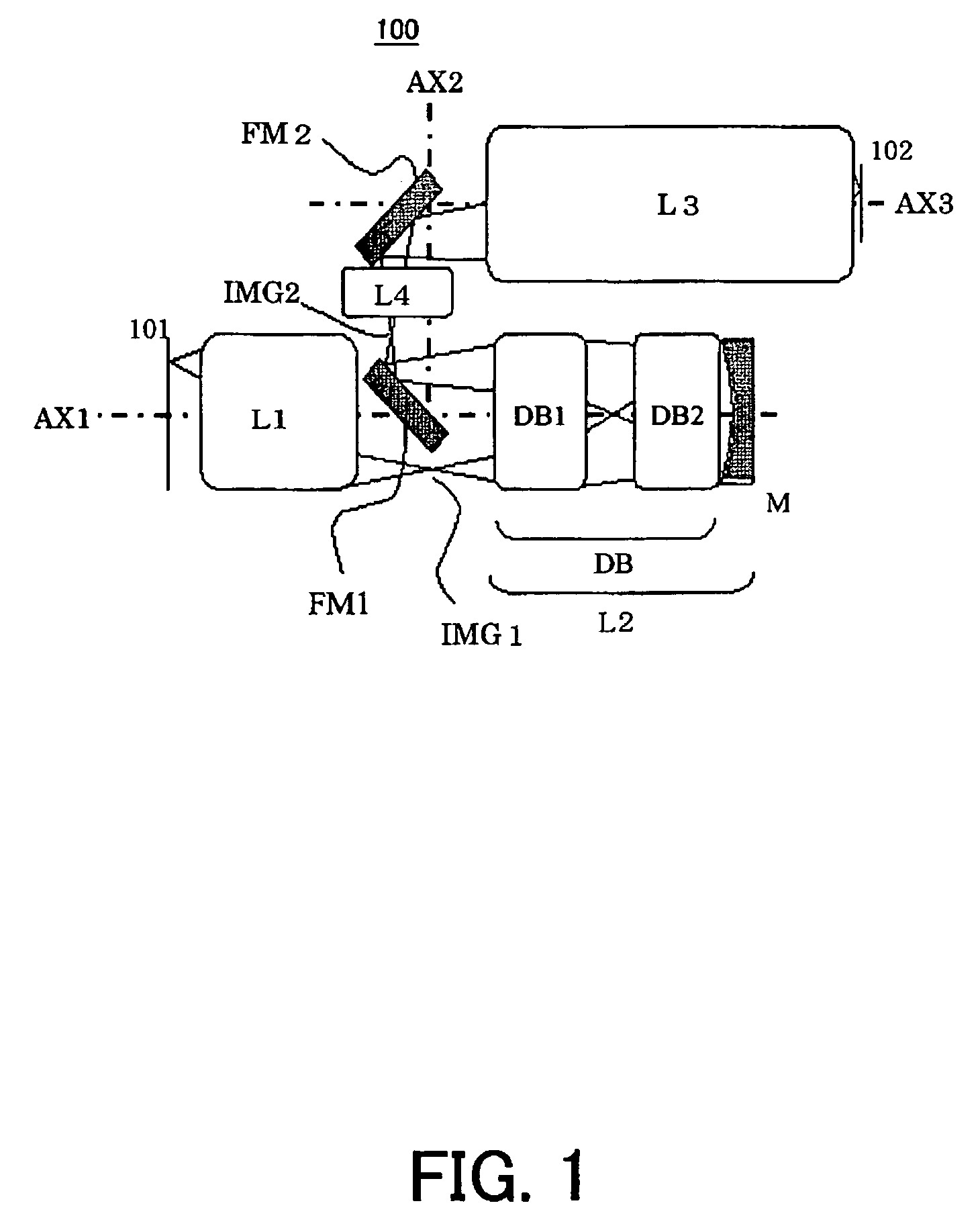
[0072]FIG. 3 is an optical-path diagram showing a specific lens configuration of the projection optical system 100 of the first embodiment. Referring to FIG. 3, the catadioptric projection system 100 includes, in order from the first object 101 side, a first lens unit L1 that does not form a reciprocating optical system, a catadioptric unit L2 that forms a reciprocating optical system, a second lens unit L3 that does not form a reciprocating optical system, and a third lens unit L4 that does not form a reciprocating optical system.

[0073] The lens unit L1 includes a dioptric lens unit having at least one lens. The catadioptric unit L2 includes a fourth lens unit DB that forms a reciprocating optical system and a concave mirror M. The lens unit DB includes a fifth lens unit DB1 that has a positive refractive power and includes at least one lens having a positive refractive power, and a sixth lens unit DB2 that has a negative refractive power and includes at least one lens having a po...

second embodiment

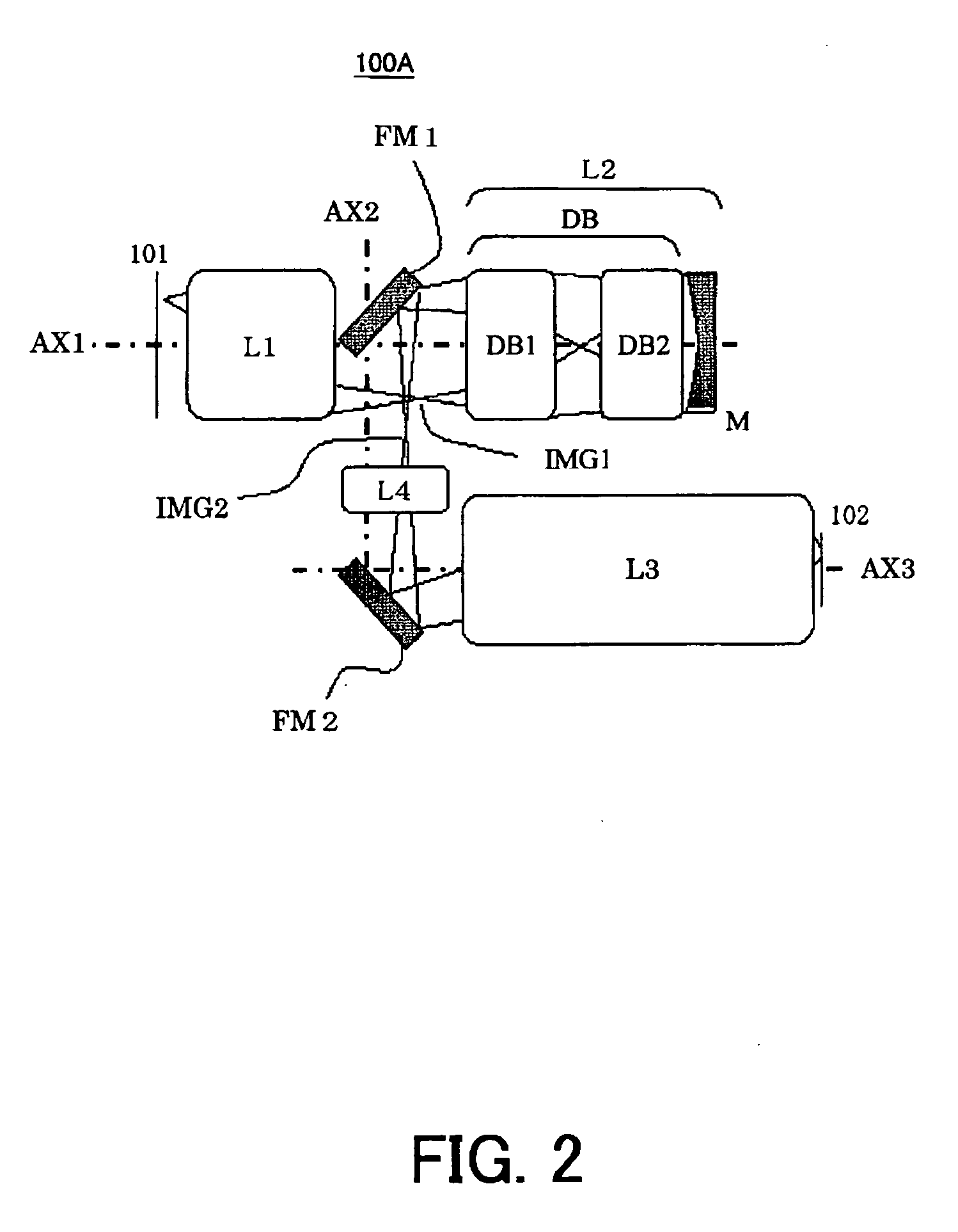
[0090]FIG. 5 is an optical-path diagram showing a specific lens configuration of the projection optical system 100 of the second embodiment. Referring to FIG. 5, the projection optical system 100 includes, in order from the first object 101 side, a first lens unit L1 that does not form a reciprocating optical system, a catadioptric unit L2 that forms a reciprocating optical system, a second lens unit L3 that does not form a reciprocating optical system, and a third lens unit L4 that does not form a reciprocating optical system.

[0091] The lens unit L1 includes a dioptric lens unit having at least one lens. The catadioptric unit L2 includes a fourth lens unit DB that forms a reciprocating optical system and a concave mirror M. The lens unit DB includes a fifth lens unit DB1 having a positive refractive power, and a sixth lens unit DB2 having a negative refractive power. The lens unit L3 is a dioptric unit that includes at least one lens.

[0092] The first and second deflective reflect...


PUM


Abstract

A catadioptric projection system for forming an intermediate image of a first object plural times, and images the intermediate image onto a second object includes at least two deflective reflectors, a lens unit arranged in an optical path between the two deflective reflectors, the lens unit having a negative refractive power, and not forming a reciprocating optical system that passes incident light and reflected light.

Description

BACKGROUND OF THE INVENTION [0001] The present invention relates generally to a projection optical system, and more particularly to a catadioptric projection system that uses a mirror to project a pattern onto a substrate, such as a single crystal substrate for a semiconductor wafer, and a glass plate for a liquid crystal display (“LCD”). The present invention is suitable, for example, for a so-called immersion exposure apparatus that immerses the final surface of the projection optical system and the surface of the substrate in the fluid or liquid, and exposes the substrate via the fluid. [0002] A reduction projection exposure apparatus has been conventionally employed which uses a projection optical system to project a circuit pattern of a mask (reticle) onto a wafer, etc. to transfer the circuit pattern, in manufacturing such a fine semiconductor device as a semiconductor memory and a logic circuit in the photolithography technology. As the high integration of the semiconductor d...

Claims


Application Information

Patent Timeline
IPC IPC(8): G02B3/00
CPCG02B17/08G02B17/0892G03F7/70225G03F7/70275G03F7/70341
Inventor KATO, TAKASHITERASAWA, CHIAKI
Owner CANON KK
Learn More