Image processing apparatus and method
- Summary
- Abstract
- Description
- Claims
- Application Information
AI Technical Summary
Benefits of technology
Problems solved by technology
Method used
Image

Examples
first embodiment
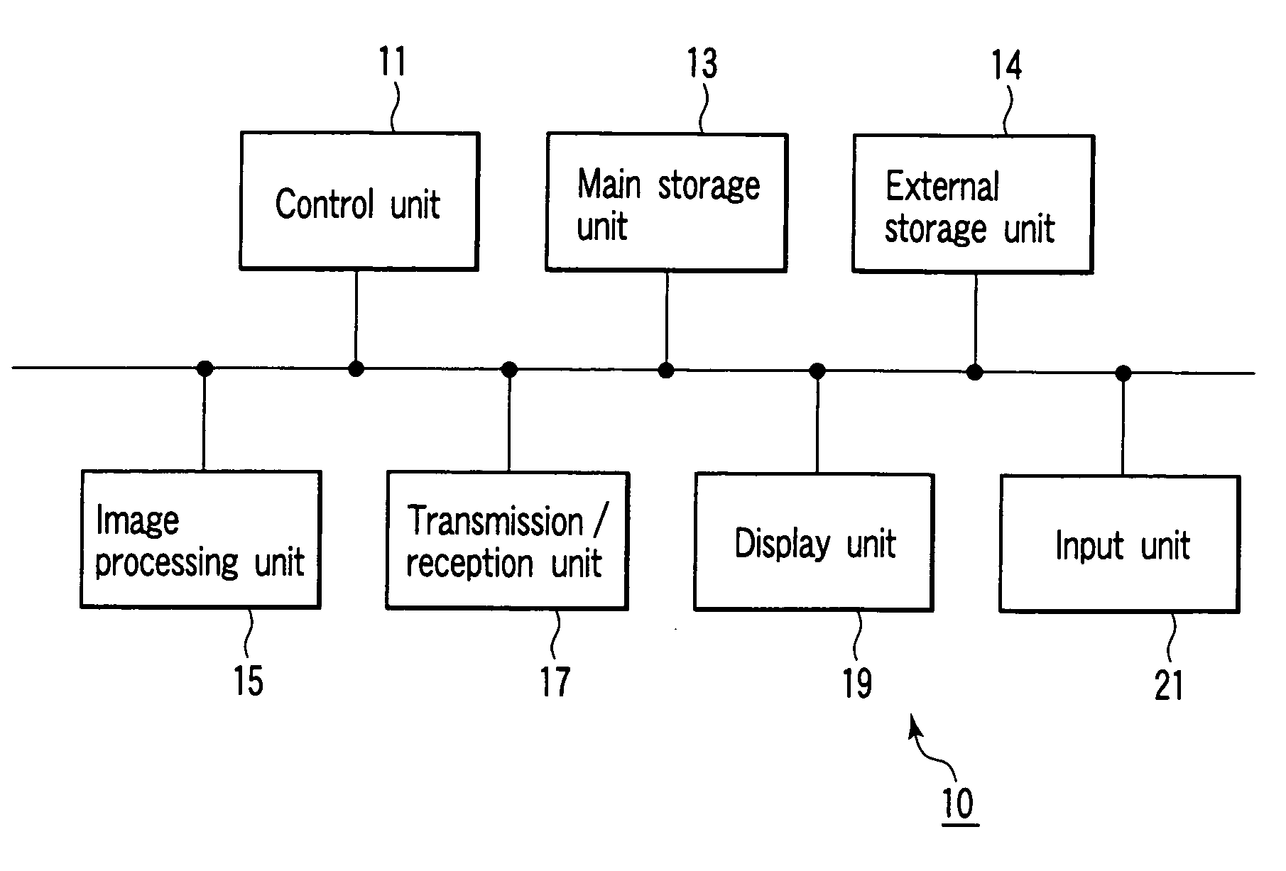
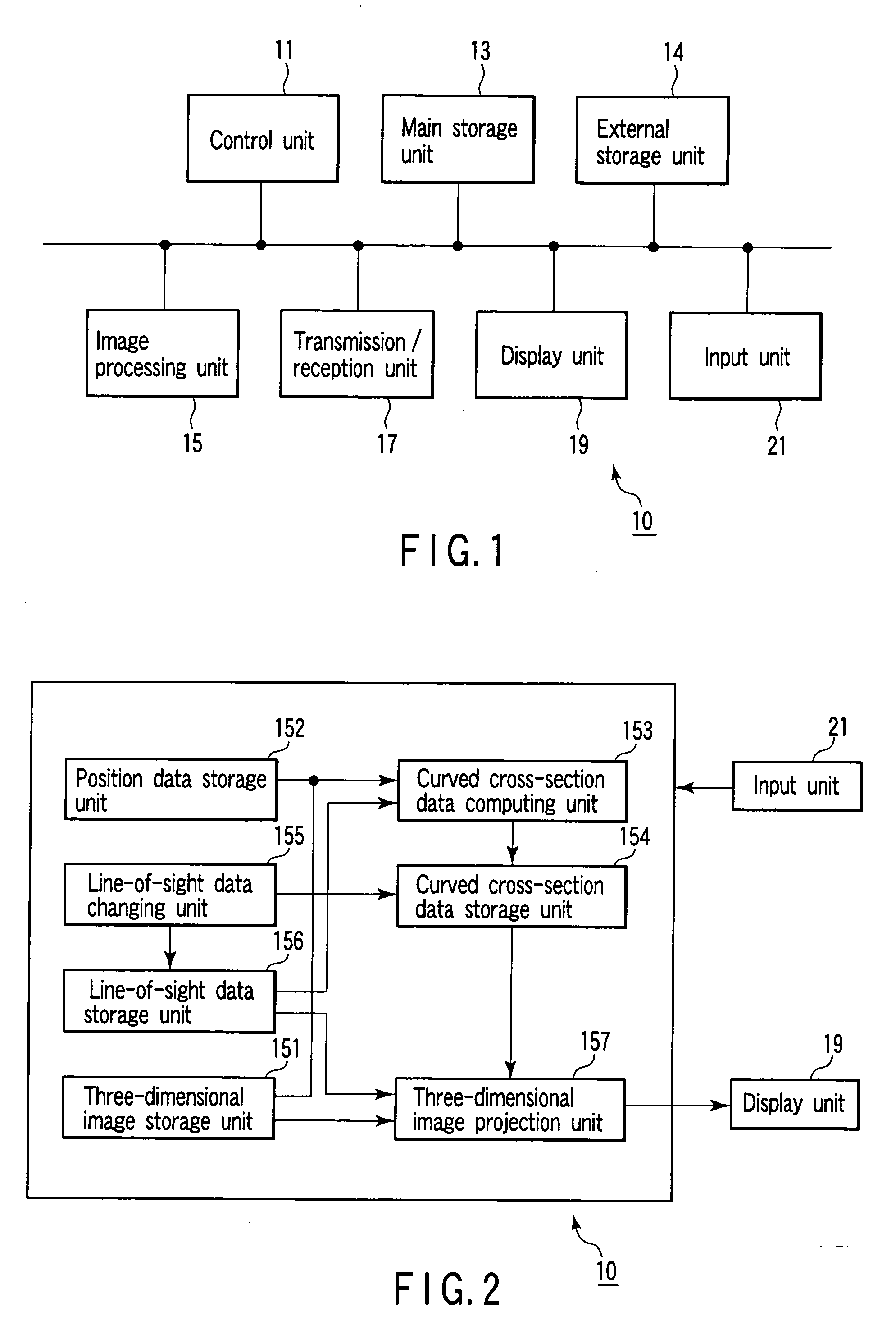
[0039]FIG. 1 is a block diagram of an image processing apparatus 10 according to this embodiment. As shown in FIG. 1, the image processing apparatus 10 comprises a control unit 11, main storage unit 13, external storage unit 14, image processing unit 15, transmission / reception unit 17, display unit 19, and input unit 21.
[0040] The control unit 11 serves as a control center to statically or dynamically control the image processing apparatus 10.
[0041] The main storage unit 13 stores the image data (irrespective of before or after reconstruction) acquired by various kinds of modalities which are received by the transmission / reception unit 17 through a network. The main storage unit 13 stores a dedicated program for executing curved cross-sectional image generation processing (to be described later).
[0042] The external storage unit 14 is a recording medium such as a magnetic disk (e.g., a floppy disk or hard disk), an optical disk (e.g., a CD-ROM or DVD), or a semiconductor memory. T...
modification 1
(Modification 1)
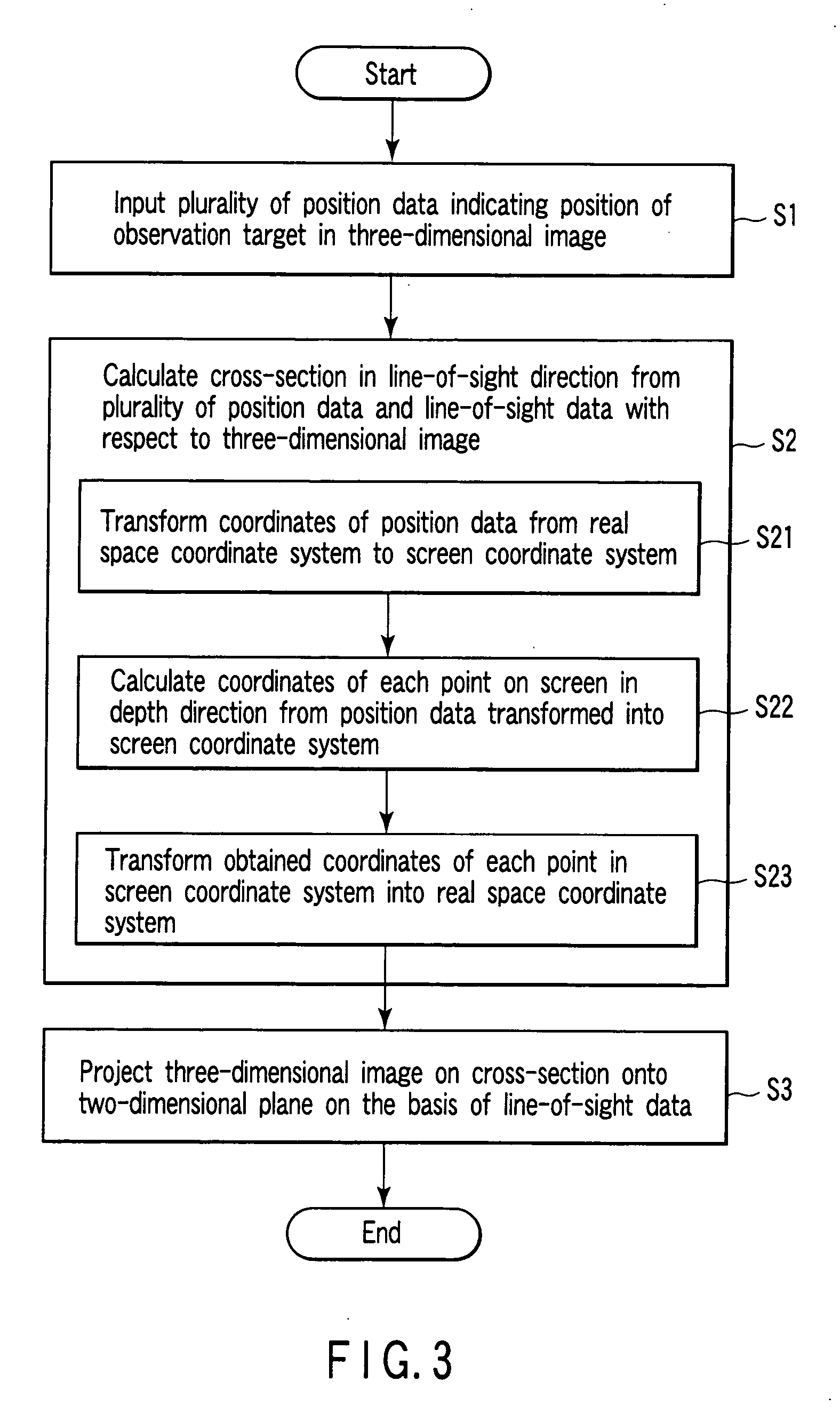
[0079] A modification of this embodiment will be described next. In this modification, a projection method of performing projection with a thickness being provided for the curved cross-section obtained in step S2 is used in step S3.
[0080] That is, predetermined thicknesses are provided for the front and back sides on the curved cross-section obtained in step S2 in the line-of-sight direction so as to set a projection area with a thickness corresponding to L voxels. The maximum voxel value of those of voxels which are located on a line of sight perpendicular to each point on the screen and fall within a projection area through which the line of sight passes is projected as the pixel value of the corresponding point on the screen. This processing is known well as maximum intensity projection.
[0081]FIG. 5C shows an image obtained in this modification by setting L=20 using the same three-dimensional CT image and blood vessel center line data as those in FIG. 5A. Referr...
modification 2
(Modification 2)
[0083] Another modification of this embodiment will be described next. In this modification, a line-of-sight direction can be arbitrarily changed.
[0084] That is, the line-of-sight data changing unit 155 calculates an amount of change in line of sight on the basis of a line-of-sight direction change instruction (e.g., an instruction to move a pointer by a predetermined amount in a predetermined direction) from the input unit 21 such as a mouse or trackball, and generates new line-of-sight data.
[0085] The transmission / reception unit 17 calculates curved cross-section data on screen coordinates on the basis of the changed line-of-sight direction. The three-dimensional image projection unit 157 generates a projection image by projecting a curved cross-section in the real space on the basis of the changed line-of-sight direction. The obtained projection image is displayed on the display unit 19 in a predetermined form.
[0086] When the above series of processing is repea...
PUM
 Abstract
Description
Claims
Application Information
PatSnap Eureka turns technology decisions into work you can execute. Powered by our Innovation Knowledge Graph, it runs expert workflows across engineering, life sciences, materials and intellectual property. Get your review-ready output in minutes.


