Honeycomb structure

Active Publication Date: 2006-05-18
NGK INSULATORS LTD
View PDF35 Cites 24 Cited by
  • Summary
  • Abstract
  • Description
  • Claims
  • Application Information

AI Technical Summary

Benefits of technology

[0037] By employing such a constitution, the coating material can have improved coatability and improved spreadability.
[0038] As described above, according to the present invention, there is provided a honeycomb structure which is useful particularly as a filter for capturing, for example, particulates

Problems solved by technology

However, the bonding material gives rise, during its kneading, to a change of state caused by the addition of an organic binder, that is, viscosity increase at the start of kneading and viscosity decrease during continued knead

Method used


Image

  • Honeycomb structure
  • Honeycomb structure
  • Honeycomb structure

Examples


examples

[0071] The present invention is described more specifically below by way of Examples. However, the present invention is in no way restricted by these Examples.

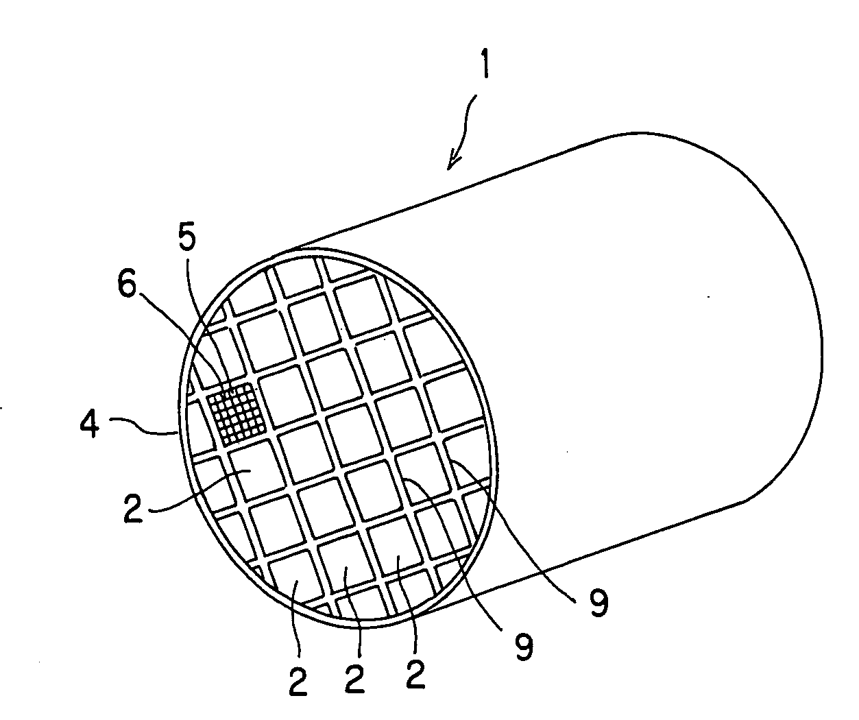
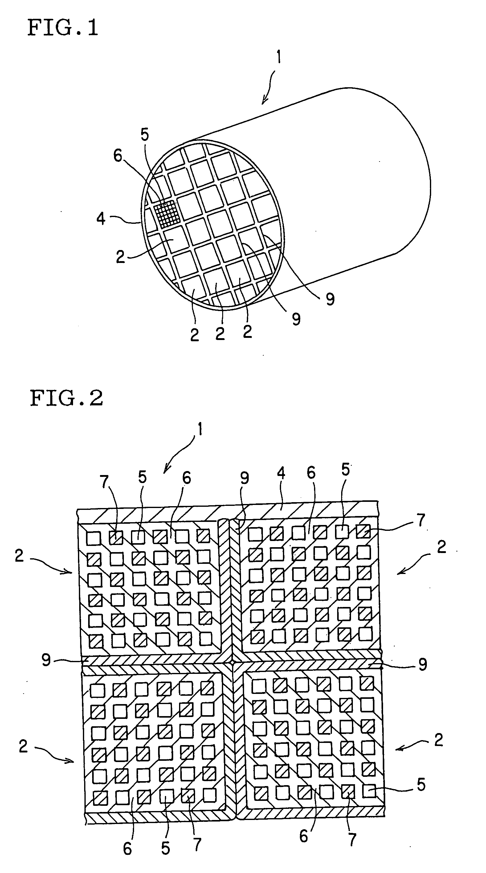
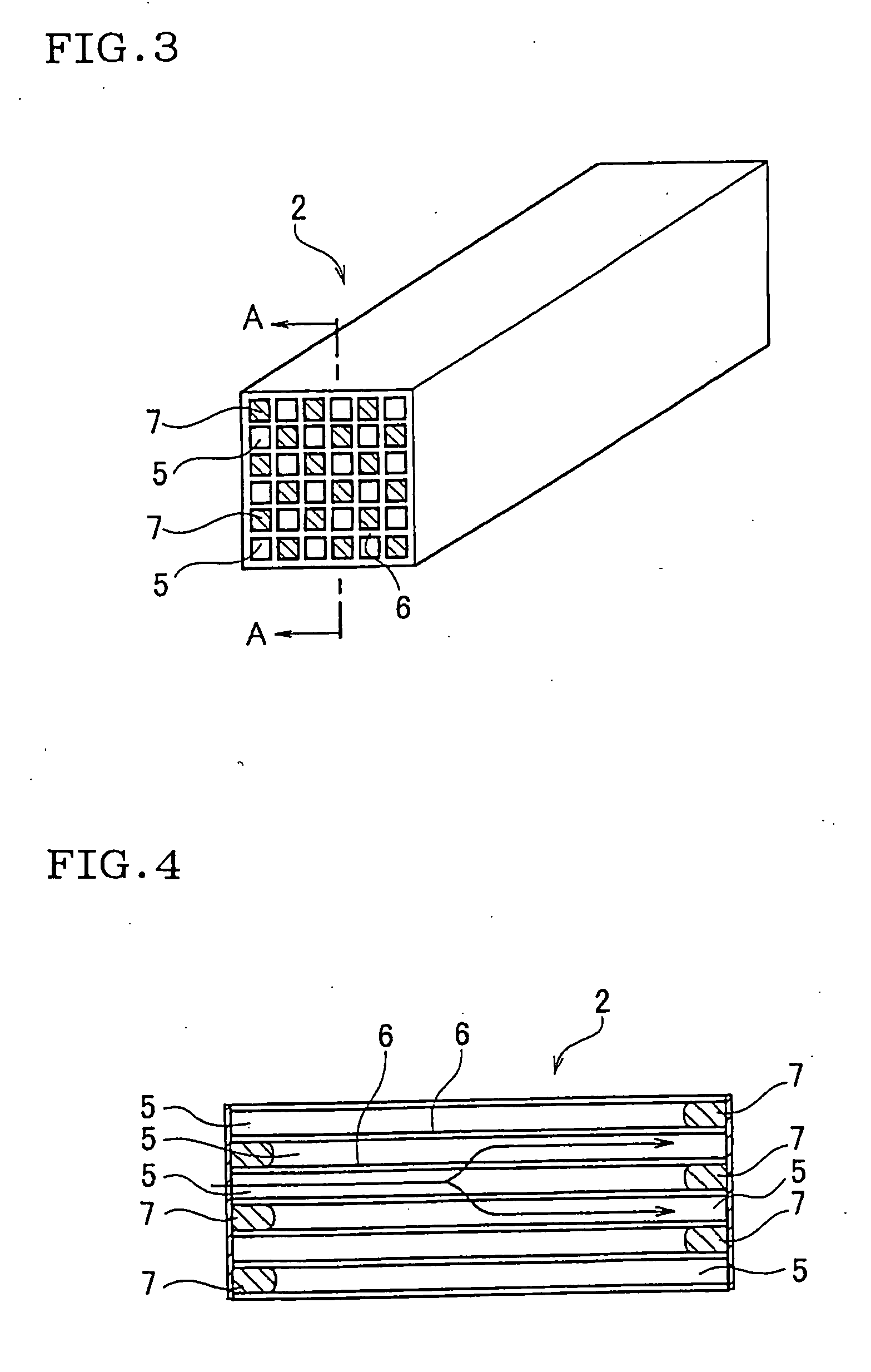
[0072] In the present Examples, a SiC powder and a Si powder both as a raw material were mixed at a weight ratio of 80:20. To the resulting mixture were added starch and a foamed resin (both as a pore former), methyl cellulose and hydroxy propoxyl methyl cellulose, a surfactant and water to prepare a plastic body. The body was extruded and the extrudate was dried by a microwave and hot air to obtain a honeycomb segment having a partition wall thickness of 310 μm, a cell density of about 46.5 cells / cm2 (300 cells / in.2), a square sectional shape of 35 mm×35 mm, and a length of 152 mm.

[0073] The honeycomb segment was plugged at each end face by using the same material as used in production of the honeycomb segment, in such a way that one cell was open at one end face and plugged at other end face, any cell adjacent thereto was ...


PUM

PropertyMeasurementUnit
Diameteraaaaaaaaaa
Percent by volumeaaaaaaaaaa
Structureaaaaaaaaaa

Abstract

The honeycomb structure of the present invention has a construction wherein a plurality of cells 5 each functioning as a passage of a fluid, surrounded by porous partition walls 6 are arranged so as to be parallel to each other in the central axis direction of the honeycomb structure, and has such a constitution that a plurality of honeycomb segments 2 are bonded integrally by a bonding material 9 containing a ceramic as a main component and a particulate filler. In the honeycomb structure, generation of drawbacks such as peeling of bonded area, cracking and the like is suppressed reliably, and the honeycomb structure is superior in durability.

Description

TECHNICAL FIELD [0001] The present invention relates to a honeycomb structure wherein a plurality of honeycomb segments are bonded integrally by a bonding material. More particularly, the present invention relates to a honeycomb structure which is useful particularly as a filter for capturing, for example, the particulate present in an exhaust gas, in which the generation of drawbacks (e.g. peeling of bonded area and cracking) after bonding with bonding material, or the generation of drawbacks (e.g. small holes and cracking) after coating with coating material is suppressed reliably, and which is superior in durability. BACKGROUND ART [0002] As a filter for exhaust gas, a diesel particulate filter (DPF), for example, is incorporated in, for example, the exhaust gas system of diesel engine in order to capture and remove the particulate contained in the exhaust gas emitted from the diesel engine or the like. Filters for exhaust gas such as the above DPF and the like are constituted by...

Claims


Application Information

Patent Timeline
IPC IPC(8): E04B1/70C04B35/565C04B35/63C04B35/80C04B37/00C04B38/00F01N3/022
CPCB32B2315/02C04B35/565C04B35/62625C04B35/6263C04B35/62655C04B35/6316C04B35/806C04B37/005C04B38/0019C04B2111/00793C04B2235/3418C04B2235/349C04B2235/428C04B2235/5228C04B2235/77C04B2235/80C04B2235/96C04B2237/083C04B2237/365F01N3/0222C04B35/573C04B38/0645C04B38/067Y02T10/20Y10S55/30C04B35/80Y02T10/12B01D39/00B01D53/34C04B37/00
Inventor MASUKAWA, NAOSHIICHIKAWA, SHUICHI
Owner NGK INSULATORS LTD
Why Eureka
Try Eureka