
Hydrogel-driven micropump

a technology of micro-pump and hydrogel, which is applied in the direction of positive displacement liquid engine, separation process, instruments, etc., can solve the problems of limited application and difficult implementation of control and detection applications, and achieve the effects of low voltage, low power consumption and easy combination with any devi

Inactive Publication Date: 2006-05-18
IND TECH RES INST
View PDF4 Cites 20 Cited by
  • Summary
  • Abstract
  • Description
  • Claims
  • Application Information

AI Technical Summary

Benefits of technology

The present invention is a micropump that uses low voltage and low power consumption, making it easy to combine with other low-voltage, low-power devices. It uses hydrogel to drive fluid by expanding and contracting through an electrophoretic process. The micropump is manufactured using a micromechanical working process, which allows for the production of thousands or even millions of samples on a single chip. The micropump is suitable for portable, safe devices and can be easily integrated with other microvalves, flow rate meters, and microchannels. The invention is operated by expanding and contracting the hydrogel using electrophoresis, which changes the liquid absorption of the hydrogel and deforms it, thus driving the fluid. The micropump is produced using bulk micromachining, which allows for the separate manufacturing of each component and the assembly of them with membranes and hydrogel, resulting in good system integration.

Problems solved by technology

A high working voltage requires a complicated power supply, which does not fit into a portable device, making control and detection applications hard to implement, so that applications are limited.

Method used


Image

  • Hydrogel-driven micropump
  • Hydrogel-driven micropump
  • Hydrogel-driven micropump

Examples


Embodiment Construction

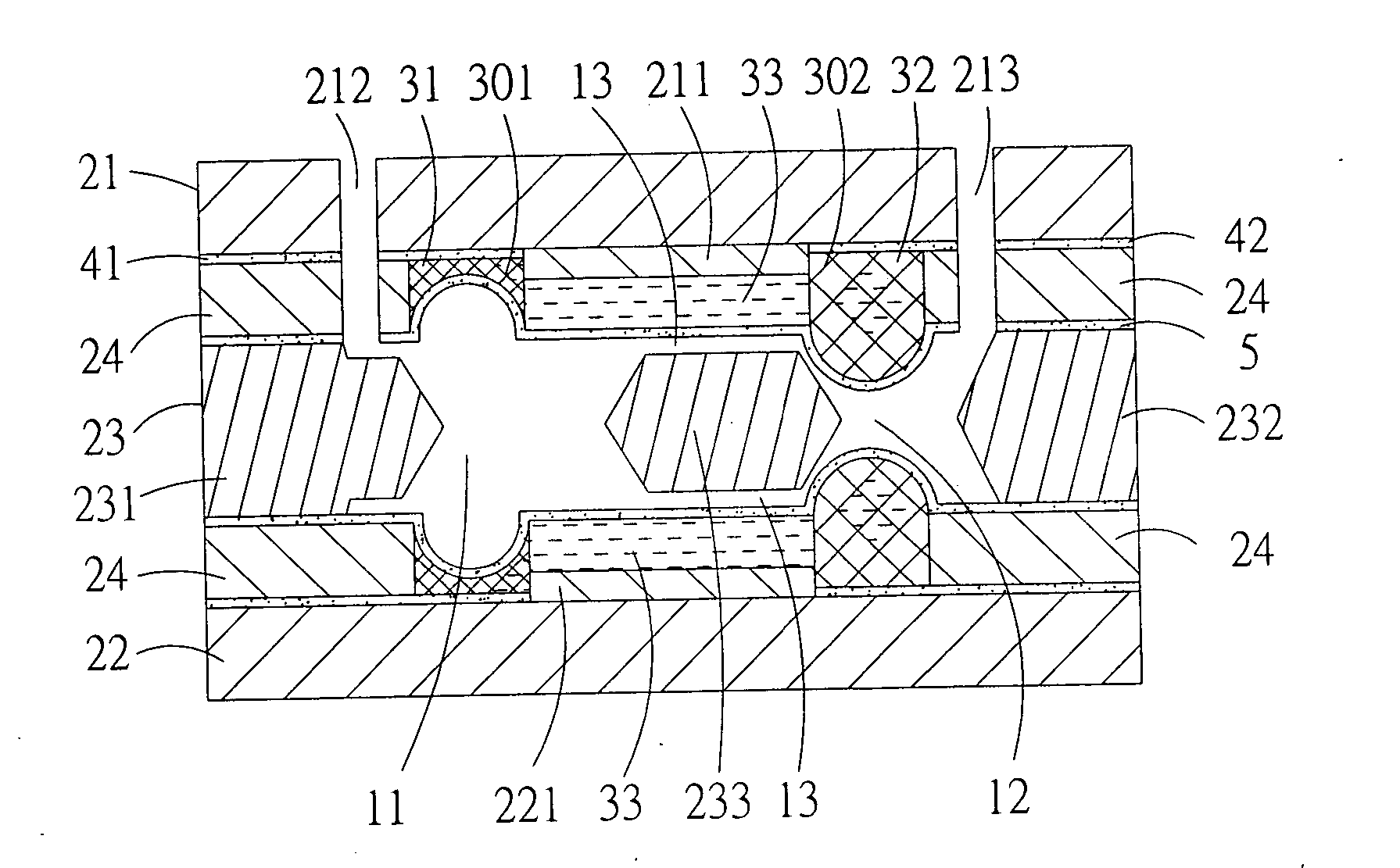
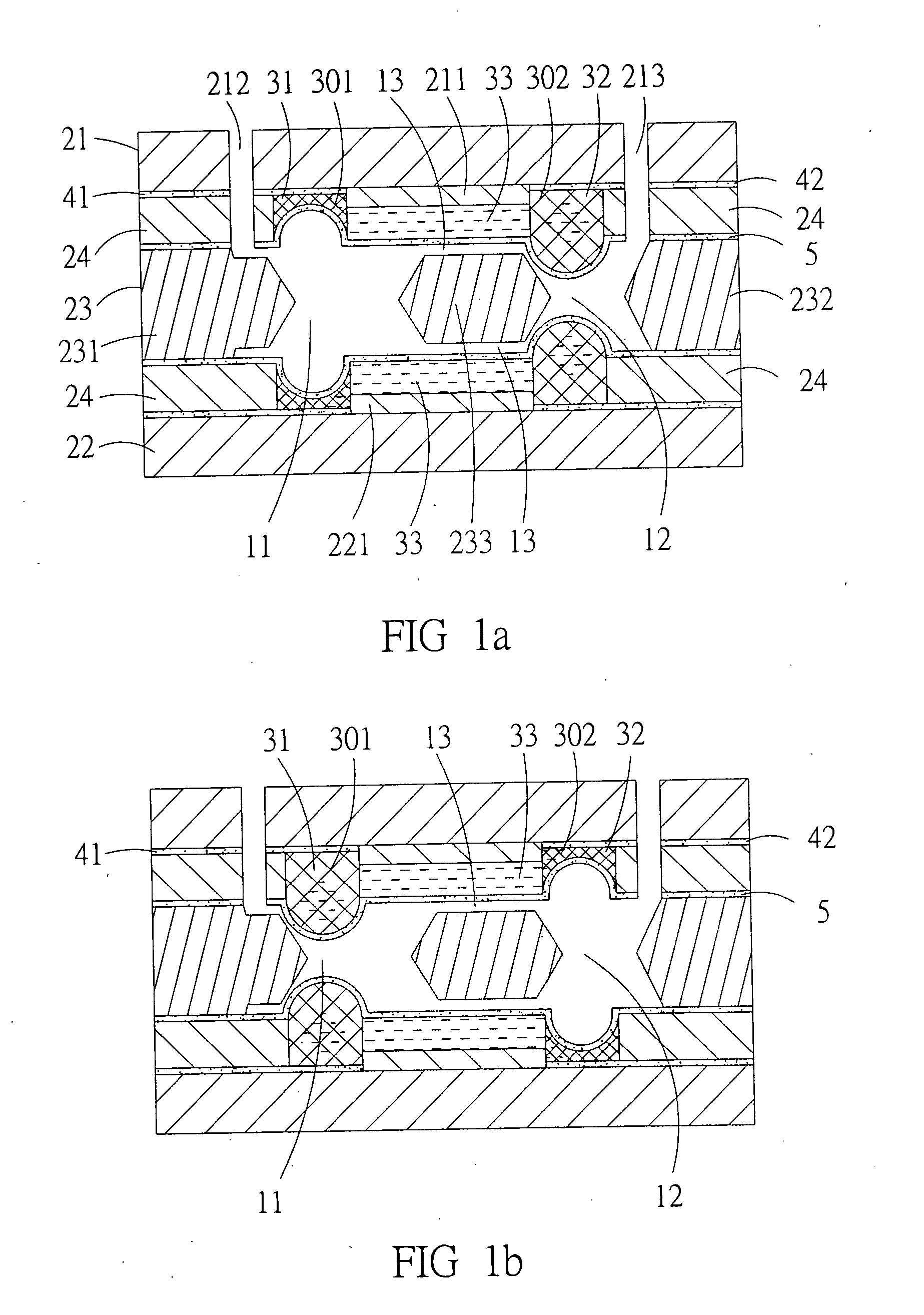
[0019] Hydrogel is a polymeric material having a fine net-like structure and being able quickly to absorb a quantity of liquid of dozens of the original mass. Having absorbed water, hydrogel expands, and after having released water, hydrogel shrinks. Therefore, by varying the quantity of absorbed water, the volume of a piece of hydrogel is changeable. Hydrogel is made of polyacrylamide-co-acrylic acid. Absorption of water until saturation and subsequent volume change happen very fast. The fastest rate is absorption of a 70-fold mass of water within one minute, accompanied by a volume increase of 100% per second.

[0020] Electrophorese usually needs application of several hundred volts for allowing ions to separate by a sufficient distance between electric terminals. For example, for separating hemo-proteins, a distance of several centimeters to several tens of centimeters is required.

[0021] When electrophorese is performed, positive ions are by an applied electric field moved toward...


PUM

PropertyMeasurementUnit
applied voltageaaaaaaaaaa
voltageaaaaaaaaaa
flow rateaaaaaaaaaa

Abstract

A hydrogel-driven micropump, comprising: two fluid chambers; a fluid channel, connecting the two fluid chambers; a first substrate plate and a second substrate plate, which are glass wafers produced by micromechanical working, each having accommodation chambers which are filled in hydrogel which are placed next to the two fluid chambers and connected by inward extending bridges, with electric terminals leading to the accommodation chambers; a middle substrate, sandwiched between the first and second substrate plates and made by a bulk micromachining process, having separated accommodation chambers close to ends thereof. A separating block is placed between the accommodation chambers. The middle substrate between the first and second substrate plates forms a micropump body. All of the substrates are separated by membranes. The accommodation chambers for electrophoretic fluid are located between the membranes and the first and second substrate plates, respectively, and insulating material. An electrophoretic fluid channel is left between the membranes and the bridges. The fluid channel is placed within the middle substrate between the membranes. The first substrate plate has through holes from outside to the two fluid chambers, allowing fluid to be injected.

Description

[0001] This is a continuation-in-part application of applicant's U.S. patent application Ser. No. 10 / 162,842 filed on Jun. 4, 2002.BACKGROUND OF THE INVENTION [0002] 1. Field of the Invention [0003] The present invention relates to a hydrogel-driven micropump, particularly to a hydrogel-driven micropump. [0004] 2. Description of Related Art [0005] A small-scale fluid system mainly comprises a micropump, a microvalve, a flow rate meter, a microchannel, and a fluid mixing device. Using a micromechanical process and technique (MEMS), various small-scale fluid driving chips are produced for applications in biotechnology, for portable environmental detection devices, precise flow control or fluid driving systems, following a tendency to ever smaller dimensions. Micropumps are important components of small-scale fluid systems for driving fluid and have been used in conjunction with micro total analysis systems (μTAS), lab-on-chips, medicine dosers and biochip systems. [0006] For producing...

Claims


Application Information

Patent Timeline
Patent Type & Authority Applications(United States)
IPC IPC(8): G01N27/447
CPCF04B19/006F04B19/24F04B43/043
Inventor LIANG, MORRISFAN, FRANKCHEN, WAE-HONGE
Owner IND TECH RES INST
Learn More