Aquarium filter

a filter and aquarium technology, applied in the field of aquarium filters, can solve the problems of turbulence or current, ‘dead’ spots in the aquarium where water can stagnate, ‘dead’ spots in the aquarium, etc., and achieve the effects of facilitating constant drip, facilitating water flow, and facilitating constant drip

Inactive Publication Date: 2006-05-18
HOCHANG BRADLEY EARL +1
View PDF13 Cites 2 Cited by
  • Summary
  • Abstract
  • Description
  • Claims
  • Application Information

AI Technical Summary

Benefits of technology

[0017] One aspect of the present invention is at least one surface skimmer. The surface skimmer is formed when the water level is raised above a threshold causing the water to cascade over the threshold in a manner similar to the way water flows over a spillway. One advantage of the present invention is that the surface skimmer traps and removes proteins and debris caught in the surface tension of the water. Another advantage of the present invention is that the surface skimmer pulls water from the surface of the tank, which has had direct exposure to oxygen, thus providing more oxygen for aquatic life and beneficial microbes.
[0018] In one embodiment of the present invention, at least one mechanical filter is utilized. The at least one mechanical filter may be located in any portion of the present invention. In an exemplary embodiment of the present invention, the at least one mechanical filter receives and filters water after passing over the surface skimmer but before flowing onto the drip plate. The at least one mechanical filter may be comprised of felt or other suitable material known in the art used to mechanical filter un-dissolved debris. In another exemplary embodiment of the present invention, a plurality of mechanical filters may be placed in multiple portions of the present invention. Drip Tray
[0019] Another aspect of the present invention is a drip tray. In an exemplary embodiment, at least one drip tray is mounted substantially horizontal to the base of the aquarium. The drip tray comprises a plurality of holes randomly located as to facilitate even flow of water through the drip tray. In an exemplary embodiment, the size of the plurality of holes may be of a diameter to facilitate a constant drip while pooling water on the surface of the drip tray. The pooling of the water may be just enough as to cover the drip tray surface, however not enough to raise the level of the pooled water on the drip tray surface. In an exemplary embodiment, a plurality of drip trays may be placed substantially parallel to each other as to create a plurality of drip tray layers. Each of these drip tray layers may be in communication with biomedia material.
[0020] One advantage of the present invention in pooling the water on the drip tray before allowing the water to drip onto the biomedia material is to prevent a channeling effect of the water over the biomedia material. A channeling effect forms when water forms a pathway or channel where the water flows more readily than any other area or pathway. Channeling is considered to be unfavorable since the water does not circulate over the entire area of a surface and wears a channel only in one area. This effect can cause, for example, one particular area of biomedia to be worn out faster and need to be cleaned or replaced before other areas of biomedia. This effect can also cause disruptions to the delicate environment of living areas of the aquarium. The pooling allows the water to evenly disperse through all of the plurality of holes in the drip tray and then over the biomedia material, thus eliminating a channeling effect of the water. Another advantage of the present invention is that the biomedia material does not need to be replaced or maintained as often due to a channeling effect, this is explained in more detail below. Biological Filtering
[0021] Another aspect of the present invention is the biological filtering. In an exemplary embodiment of the present invention, biomedia material is in communication with and extends below the drip tray. In another exemplary embodiment of the present invention, the biomedia material comprises of a plurality of substantially perpendicular surfaces that extend substantially to the drip tray below, while still allowing flow through and pooling of water of the drip tray surfaces. One advantage to having a plurality of biomedia material is to increase the surface area and thus, increasing the filtering capability. In an exemplary embodiment of the present invention, the shape of the biomedia material may be conical, cylindrical, pyramidal, elongated, cubical, tear dropped, or any other sufficient shape as to facilitate the flow of water over the surface area of the material. In another exemplary embodiment of the present invention, the biomedia material is infinitely cross-sectioned into smaller sections as to facilitate the greatest amount of surface area possible. The biomeia material can be any material that removes biological waste including, but not limited to, materials that are known in the art.
[0022] Another advantage of the configuration and shape of the biological media is that it further prevents a channeling effect. Typically, a channeling effect in biomedia material prevents water from flowing over all portions of biomedia material evenly, thus, making the biological filtration inefficient. When typical biomedia material is stacked on top of each other, which is required to sustain aquatic life, the material becomes less effective as the chamber becomes taller because the effect of channeling becomes more pronounced as the water has more time to gather. Thus, with existing biomedia material, channeling is noticeable when the material is stacked at only a couple of inches tall. However, in the present invention, the configuration and shape of the biomedia material allows substantially infinite (in height) stacking of the material with no significant channeling effects. Because of the configuration and shape of the biological media in the present invention, water channeling is eliminated and efficiency is not reduced by vertical height.

Problems solved by technology

Typically, the water that is pumped back into the tank is no more than a few inches from the siphon tube that carries he water into the filter, causing ‘dead’ spots in the aquarium where water can stagnate.
Further, power filters typically allow debris to collect at the bottom of the aquarium.
Further, cleaning requires the disassembly and reassembly of the filter.
Similar to the power filter, the internally mounted power filter typically causes ‘dead’ spots in the aquarium where water can stagnate.
Air is forced by the pump to the air stones thereby forcing air bubbles to travel up through the tubes to the water surface creating turbulence or current.
Additionally, the surface area of the substrate in an undergravel filter can cause ‘dead’ spots in the aquarium where water can stagnate.
Similar to the power filter, the wet / dry trickle type filter typically causes ‘dead’ spots in the aquarium where water can stagnate.
Further, cleaning requires the disassembly and reassembly of the filter.
With this type of wet / dry filter, visibility through the tank is impaired due to the rear-mounting of the filter.
Similar to the power filter, this type of wet / dry filter typically causes ‘dead’ spots in the aquarium where water can stagnate.
With the exception of the wet / dry filters, none of the filters here perform biological filtration to a modicum of efficiency.
Most filters cause ‘dead’ spots in the aquarium where water can stagnate, allow debris to collect at the bottom of the aquarium, are difficult to maintain and are unsightly.
Though the wet / dry filters are somewhat efficient at biological filtration, most create a channeling effect which causes both inefficient water circulation and inefficient biological filtering of the water.
Also, most wet / dry filters are complicated to install, are expensive and have involved maintenance requirements.
They are also prone to leakage and clogging since the water is removed and then pumped back through the hoses.
Additionally, most take up space outside of the aquarium or prevent adequate visibility through the tank.
Moreover, the internally mounted filters have a limited capacity.
They do not buffer or completely filter all of the water entering the biological section.
The biological area uses ceramic blocks for bacteria beds which also create a channeling effect and tend to clog and must be replaced.
Further, though the Simplicity Plus can handle larger aquariums, they are very bulky, taking up a large portion of the living area of the aquarium and viewing through the aquarium is impaired by the rear-mounted filter design.

Method used


Image

  • Aquarium filter
  • Aquarium filter
  • Aquarium filter

Examples


Embodiment Construction

[0032] In general, the present invention can be described as a novel aquarium filter that treats water mechanically, chemically and biologically, provides maximum and uniform circulation and aeration of water, prevents channeling, reduces surface debris, reduces leaking and clogging, maximizes the viewable area, facilitates a slim profile, while being uncomplicated to install and inexpensive.

[0033] Referring now to the figures, in which like numerals refer to like elements throughout the several views, exemplary embodiments of the present invention are described.

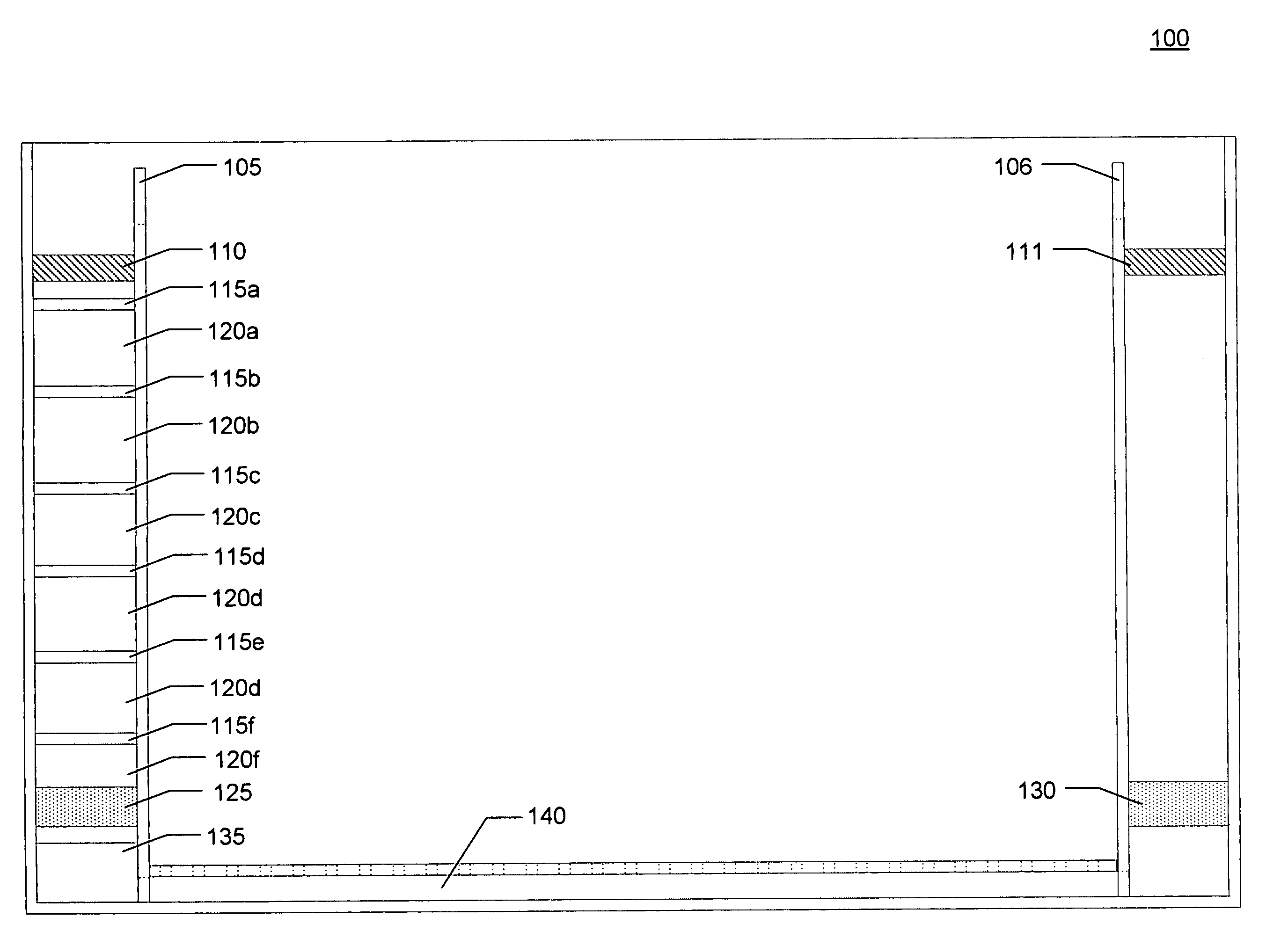
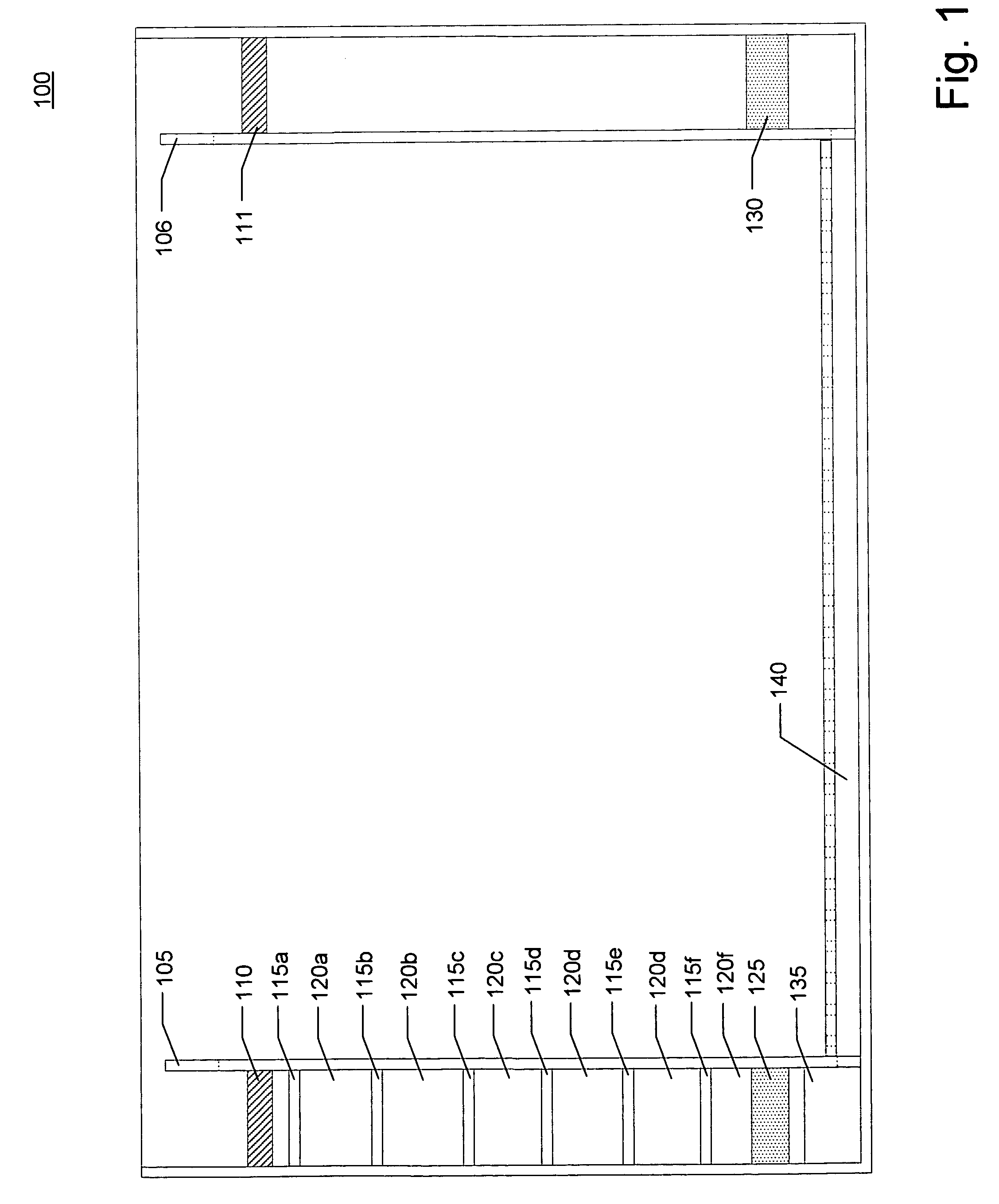
[0034] In conjunction with FIGS. 1 & 2, exemplary embodiments of the present invention are depicted by an aquarium filter 100 comprising a first surface skimmer 105, a second surface skimmer 106, a first mechanical filter 110, a second mechanical filter 111, a plurality of drip trays 115a-f, a plurality of biological filters 120a-f, a first chemical filter 125, a second chemical filter 130, a pump 135 and a conduit 140.

[0...


PUM

PropertyMeasurementUnit
chemicalaaaaaaaaaa
shapeaaaaaaaaaa
areaaaaaaaaaaa

Abstract

The present invention is an aquarium filter that treats water mechanically, chemically and biologically, provides maximum and uniform circulation and aeration of water, prevents channeling, reduces surface debris, reduces leaking and clogging, maximizes the viewable area, facilitates a slim profile, while being uncomplicated to install and inexpensive. In an exemplary embodiment, the present invention is an aquarium filter comprising a first surface skimmer, a second surface skimmer, a first mechanical filter, a second mechanical filter, a plurality of drip trays, a plurality of biological filters, a first chemical filter, a second chemical filter, a pump and a conduit.

Description

CROSS REFERENCE TO RELATED APPLICATIONS [0001] This application is related to, and incorporates by reference, U.S. patent application having Ser. No. __ / ___,___ and entitled “AQUARIUM” which is filed concurrently herewith and is assigned to the same assignee.TECHNICAL FIELD [0002] The present invention relates to aquarium filters and, more particularly to a wet / dry filter that provides filtration, aeration, and buffering, of the water while maximizing the usable area of the aquarium. BACKGROUND OF THE INVENTION [0003] Filters have been used in aquariums for many years to remove particulate matter from the aquarium water in order to keep the aquarium clean. Traditionally, the most common type of aquarium filter is a power filter which hangs on the outside of the aquarium over the top edge thereof It includes a siphon tube which carries water from the aquarium into the filter box which is located on the outside of the tank. Water entering the filter box flows over various types of fil...

Claims


Application Information

Patent Timeline
Patent Type & Authority Applications(United States)
IPC IPC(8): A01K63/04
CPCA01K63/045Y10S210/905
Inventor HOCHGESANG, BRADLEY EARLHOCHGESANG, ANDREW KENT
Owner HOCHANG BRADLEY EARL
Why Eureka
Try Eureka