Device and method for imaging a multiple particle beam on a substrate

a multi-particle beam and imaging technology, applied in the field of devices and methods for imaging multi-particle beams on substrates, can solve the problems of low productivity at the structural level of today, inability to write uninterrupted strips across the entire substrate, and inability to achieve the precise positioning of the first pixel imag

Active Publication Date: 2006-05-18
VISTEC ELECTRON BEAM
View PDF20 Cites 30 Cited by
  • Summary
  • Abstract
  • Description
  • Claims
  • Application Information

AI Technical Summary

Benefits of technology

[0031] Adjusting the offset of the sawtooth signal by subtracting the current accumulator value from the start value of the sawtooth generator at time tS at which exposur...

Problems solved by technology

Apart from the advantage that they possess high resolution, maskless particle projection systems (e-beam or ion beam writers) have the disadvantage of low productivity at the structural level of today, which is a result of the serial writing process of the particle beam.
However, this device operates using a single electron beam.
A blanking of the total beam is required for repositioning the writing fields; uninterrupted writing of a strip across the entire substrate is therefore no...

Method used


Image

  • Device and method for imaging a multiple particle beam on a substrate
  • Device and method for imaging a multiple particle beam on a substrate
  • Device and method for imaging a multiple particle beam on a substrate

Examples


Embodiment Construction

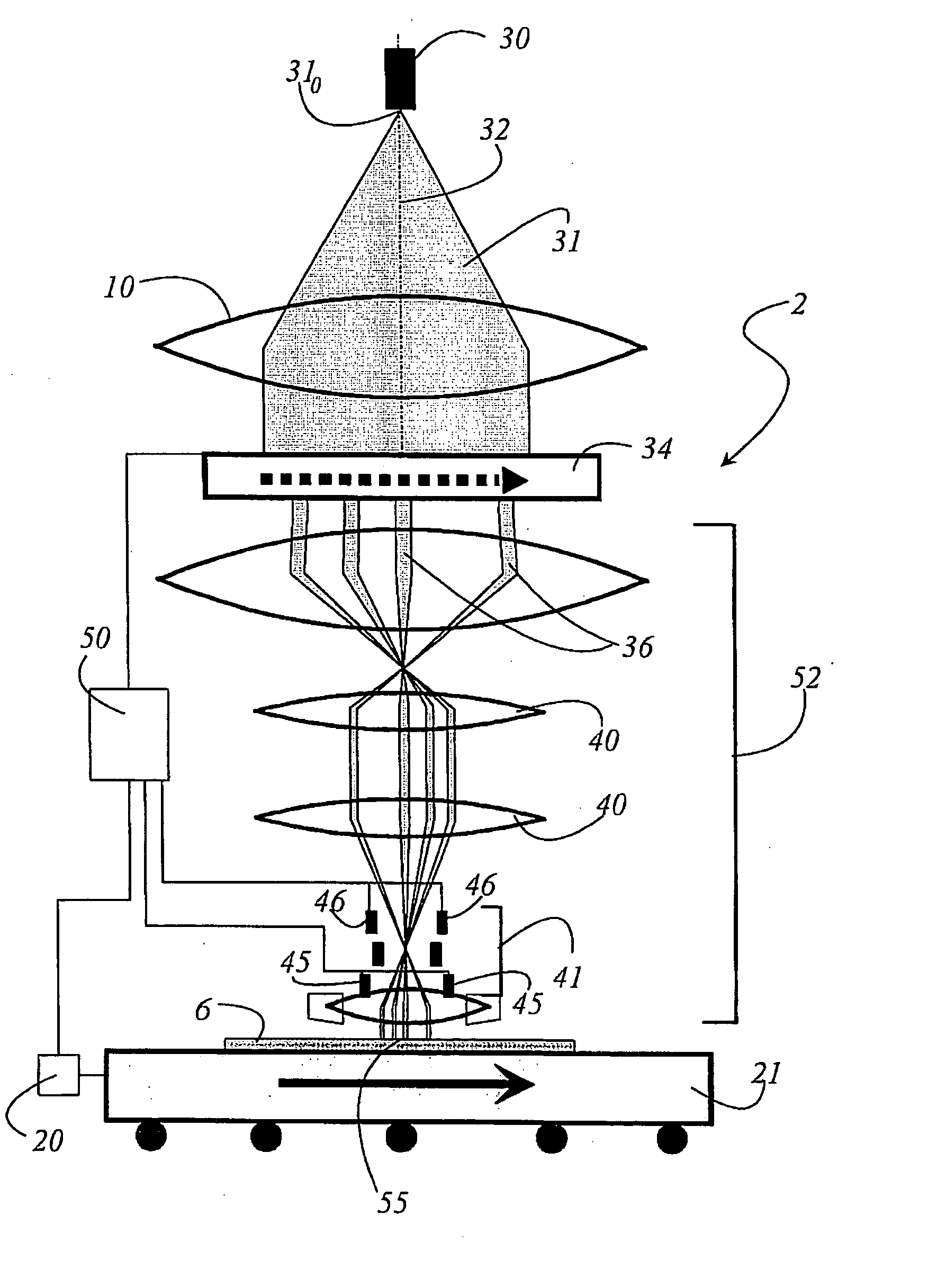
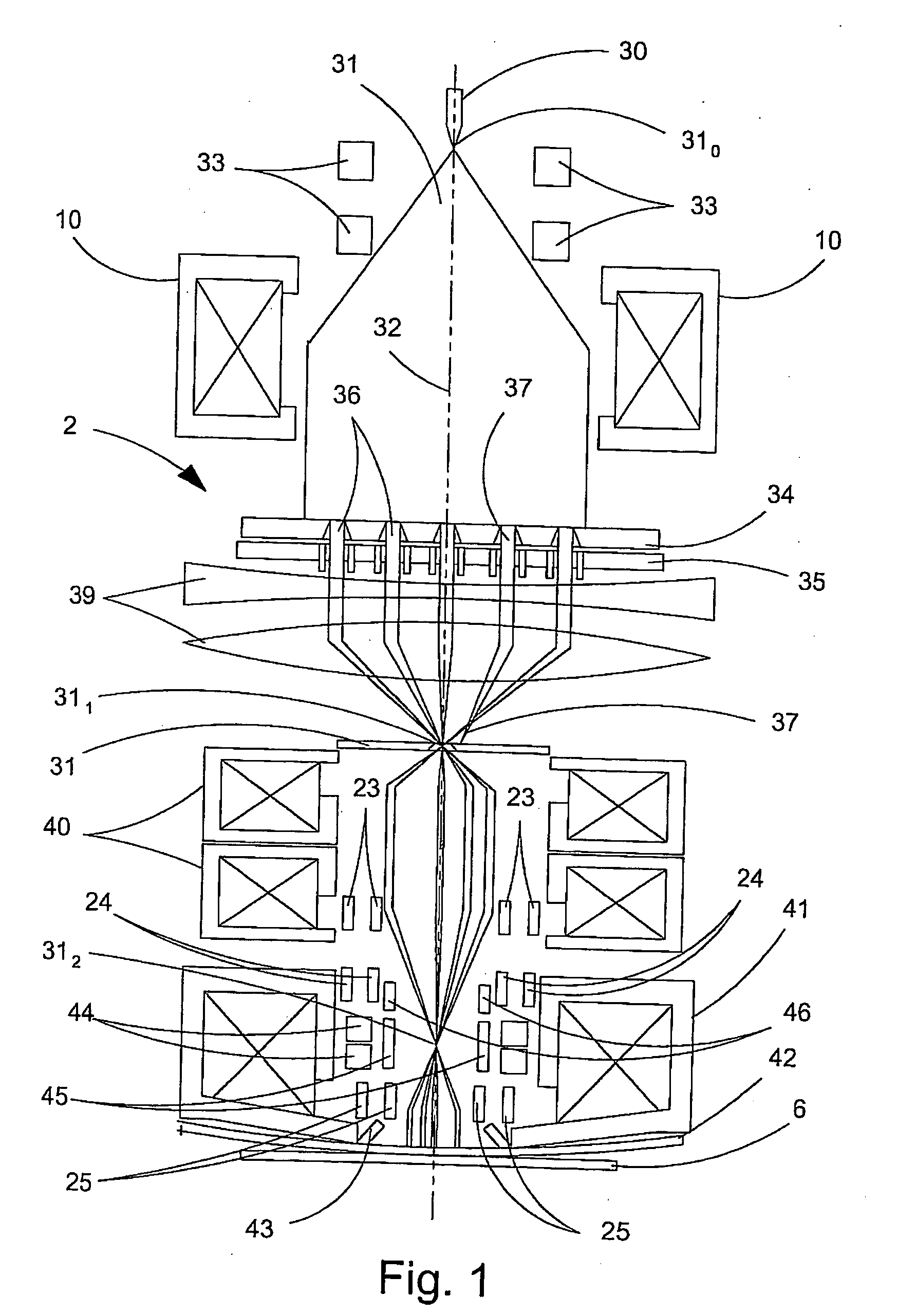
[0043]FIG. 1 shows the principal beam path of a particle projection system 2. The particle projection system 2 is then described, the particles in this case being electrons. However, this restriction to electrons should in no way be interpreted as a limitation of the invention. It is obvious that the present invention can also be implemented with particles other than electrons. An electron beam 31 that is produced by an electron cannon 30 spreads out in the direction of an electron optical axis 32. The electrons emitted by the electron cannon 30 exhibit a source crossover 310. The electron cannon 30 is connected to a beam centering device 33 that aligns the electron beam 31 symmetrically around the optical axis 32. After the beam centering device, the electron beam 31 passes through an illumination condenser 10, which forms a parallel beam from the initially divergent electron beam. The beam formed by the illumination condenser 10 possesses a diameter, across which the intensity is ...


PUM


Abstract

A device and a method for imaging and positioning a multiparticle beam on a substrate is disclosed. The device comprises a particle beam source with a condenser optic that produces a particle beam that illuminates the surface of an aperture plate. A multiplicity of individual beams are produced from the particle beam by means of the aperture plate, which are then projected by a projection system onto a substrate where they describe a beam base point. The substrate or target, respectively, is placed on a table that is movable along an x-coordinate and a y-coordinate, and that is provided with a laser path measurement system. The laser path measurement system relays positional data with a fixed clock rate to a synchronization and control device 50 that positions the beam base point along the x-coordinate and the y-coordinate via a beam tracking system, taking into account the corrective data and pixel phase, whereby precise staircase beam-to-table positioning is achieved across the entire substrate in spite of faulty table movement.

Description

RELATED APPLICATIONS [0001] This application claims priority to German patent application number DE 10 2004 055 149.9-54, filed Nov. 16, 2004, which is incorporated herein by reference in its entirety. FIELD OF THE INVENTION [0002] The invention relates to a device and a method for imaging a multi particle beam on a substrate. The device comprises a particle beam source that generates a particle beam. The surface of an aperture plate is illuminated by a particle beam via a condenser optic and generates a multiplicity of individual beams from the particle beam. A projection system projects the individual beams on a substrate, whereby the middle of the beam bundle defines a beam base point on the surface of the substrate. The substrate itself is placed on a table that is movable along a x-coordinate and along a y-coordinate and is provided with a laser path measurement system. [0003] The invention further relates to a method for positioning a multi particle beam that consists of a mul...

Claims


Application Information

Patent Timeline
IPC IPC(8): G01N23/00G01J1/00
CPCB82Y10/00B82Y40/00G01N23/04H01J37/3174
Inventor HEINITZ, JOACHIMSCHUBERT, ANDREAS
Owner VISTEC ELECTRON BEAM
Why Eureka
Try Eureka