Eureka AIR delivers breakthrough ideas for toughest innovation challenges, trusted by R&D personnel around the world.

Process for producing nanoparticle apparatus therefor and method of storing nanoparticle

a nanoparticle and apparatus technology, applied in the direction of grain treatment, chemical/physical/physical/physical-chemical process, energy-based chemical/physical/physical-chemical process, etc., can solve the problem of inadequate efficiency of nanoparticulation and achieve the effect of high efficiency

Inactive Publication Date: 2006-05-18
HAMAMATSU PHOTONICS KK
View PDF6 Cites 11 Cited by
  • Summary
  • Abstract
  • Description
  • Claims
  • Application Information

AI Technical Summary

Benefits of technology

[0007] The present inventors have found, as a result of diligent research towards resolving the above issue, that the efficiency of nanoparticulation is increased extremely by cooling a laser light irradiation portion and irradiating the portion with a laser light, and have thus come to complete the present invention.
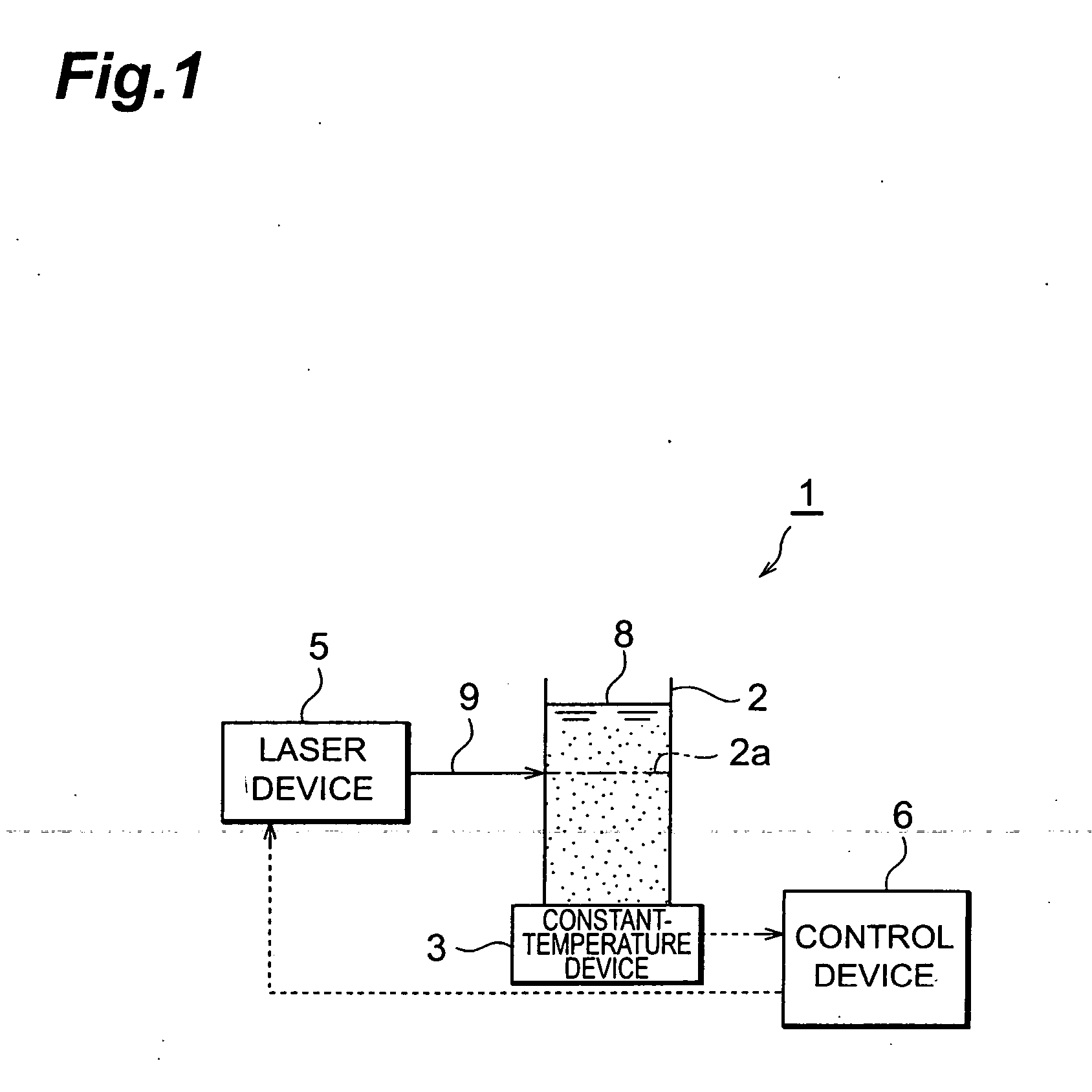
[0009] With this invention, by the to-be-treated liquid being cooled, the respective suspended particles are cooled in their entireties. When the cooled laser light irradiation portion of the to-be-treated liquid is irradiated with the laser light, the laser light is absorbed at the surfaces of the suspended particles in the laser light irradiation portion. Since the to-be-treated liquid is cooled at this time, significant temperature differences arise between the interiors and surfaces of the suspended particles and between the surfaces of the suspended particles and the to-be-treated liquid at the laser light irradiation portion. The suspended particles are thus pulverized readily and nanoparticulation of high efficiency is carried out.
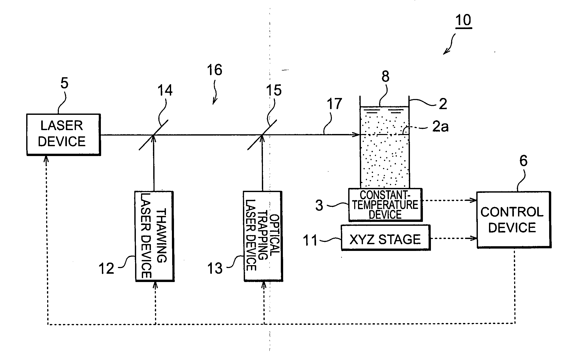
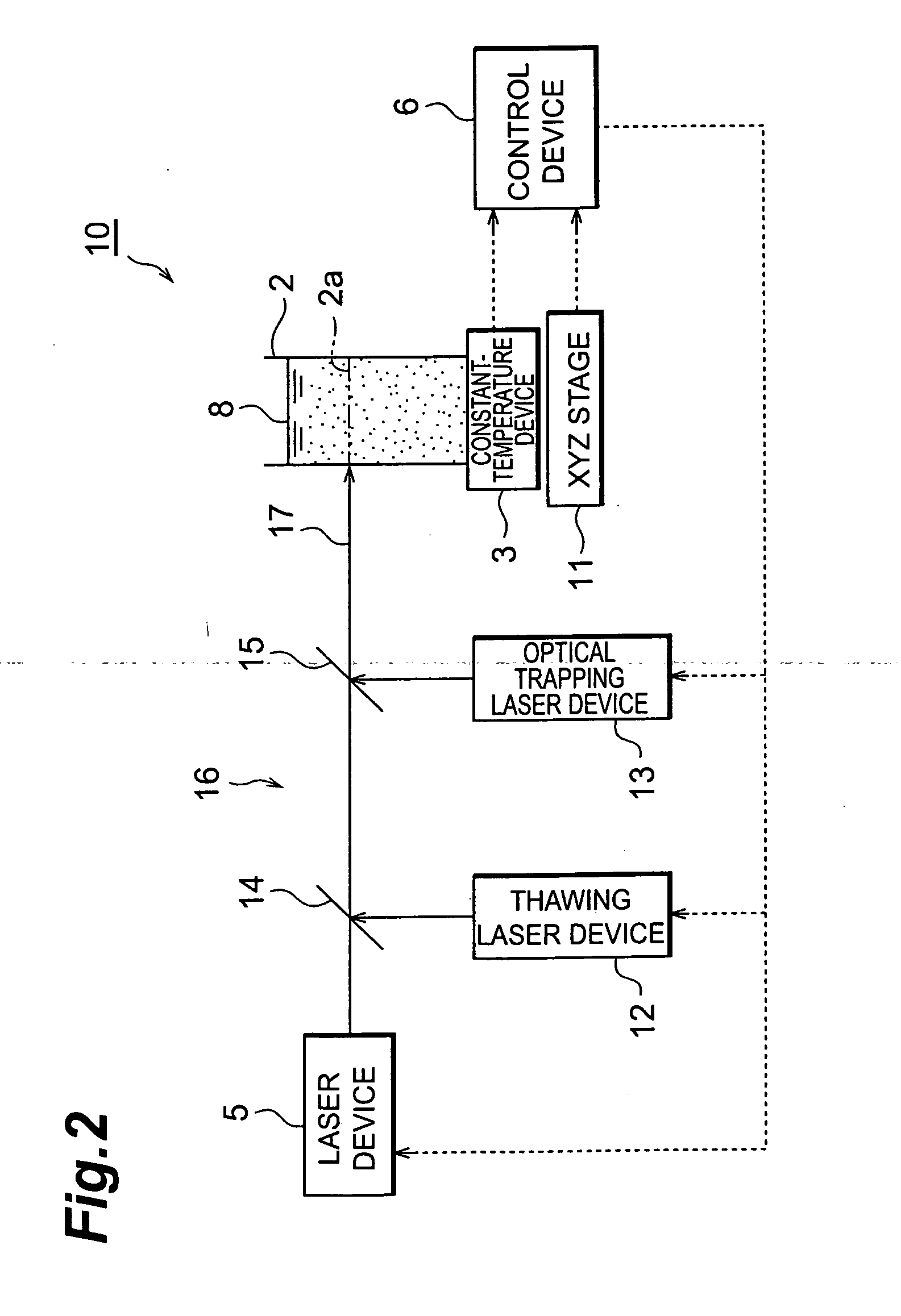
[0011] With such a device, the above-described nanoparticle production method can be carried out effectively. That is, with this invention's device, by the to-be-treated liquid being set to a low temperature by the temperature adjustment device, the respective suspended particles are cooled in their entireties. When the laser light irradiation portion of the to-be-treated liquid is then irradiated with the nanoparticle production laser light by the nanoparticle production laser device, the nanoparticle production laser light is mainly absorbed at the surfaces of the suspended particles in the laser light irradiation portion. Since the to-be-treated liquid is cooled at this point, significant temperature differences arise between the interiors and surfaces of the suspended particles and between the surfaces of the suspended particles and the to-be-treated liquid at the laser light irradiation portion. The suspended particles are thus pulverized readily and nanoparticulation of high efficiency is carried out.

Problems solved by technology

However, with the nanoparticulation method described in the above prior document, the efficiency of nanoparticulation was still inadequate.

Method used


Image

  • Process for producing nanoparticle apparatus therefor and method of storing nanoparticle
  • Process for producing nanoparticle apparatus therefor and method of storing nanoparticle
  • Process for producing nanoparticle apparatus therefor and method of storing nanoparticle

Examples


example 1

[0050] 3 ml of a sample solution, prepared by suspending a VOPc powder in water (VOPc: 0.5 mg / ml), were dispensed in a 10 mm×10 mm×40 mm rectangular quartz cell, and thereafter the temperature of the sample solution was lowered to 5° C. using a constant-temperature device (131-0040 Constant-Temperature Cell Holder with Temperature Display, made by Hitachi).

[0051] The sample solution was then irradiated with the third harmonic of an Nd:YAG laser (80 mJ / cm2·pulse, FWHM=4 ns, 20 Hz) for 15 minutes. As a result, the entirety of the sample solution became transparent. It is thus considered that nanoparticulation VOPc progressed and pseudo-dissolution of the nanoparticles occurred.

[0052] The absorbance of the sample solution after laser light irradiation was then measured by an absorbance measuring device. The result is shown in FIG. 4. As shown in FIG. 4, the absorbance was found to be significantly high in the vicinity of 500 to 900 nm, which is the absorbance wavelength range of VOPc...

example 2

[0057] In this Example, nanoparticulation treatment of VOPc was carried out as follows using the device of FIG. 2.

[0058] First, XYZ stage 11 was moved to set the laser light irradiation portion in the 10 mm×10 mm×40 mm rectangular quartz cell. 3 ml of a sample solution, prepared by suspending VOPc powder in water (VOPc: 0.5 mg / ml), was then dispensed in the rectangular quartz cell. Thereafter, using the same constant-temperature device as in Example 1, the sample solution was cooled to and solidified at −5° C., thereby obtaining a solidified body.

[0059] Then using an argon ion laser (514 nm) as thawing laser device 12, the above-mentioned laser light irradiation portion was irradiated with a thawing laser light.

[0060] Then using a YAG laser (1064 nm) as optical trapping laser device 13, an optical trapping laser light was emitted and the above-mentioned laser light irradiation portion was irradiated with the optical trapping laser light.

[0061] Lastly, using the third harmonic li...


PUM

PropertyMeasurementUnit
wavelengthaaaaaaaaaa

Abstract

With this invention, in a nanoparticle production method, wherein nanoparticles are produced by irradiating a laser light irradiation portion 2a of a to-be-treated liquid 8 with a laser light, in which suspended particles are suspended, to pulverize the suspended particles in laser light irradiation portion 2a, laser light irradiation portion 2a of to-be-treated liquid 8 is cooled. In this case, by the cooling of to-be-treated liquid 8, the respective suspended particles are cooled in their entireties. When the portion 2a of this to-be-treated liquid 8 is irradiated with the laser light, the laser light is absorbed at the surfaces of the suspended particles at portion 2a. Since to-be-treated liquid 8 is cooled during this process, significant temperature differences arise between the interiors and surfaces of the suspended particles and between the surfaces of the suspended particles and the to-be-treated liquid at laser light irradiation portion 2a, and highly efficient nanoparticulation is realized.

Description

TECHNICAL FIELD [0001] This invention concerns a nanoparticle production method and production device and a nanoparticle preservation method, and to be more specific, concerns a nanoparticle production method and production device, with which nanoparticles are produced by irradiating a laser light irradiation portion of a to-be-treated liquid with a laser light, wherein suspended particles are suspended, to pulverize the suspended particles in the laser light irradiation portion, and a nanoparticle preservation method. BACKGROUND ART [0002] Nanoparticulation brings about extreme increase of surface area. Thus with nanoparticles, the reactivity with the surroundings is thus high and properties unique to a substance are exhibited readily. Also, in the case where the particles are of a poorly soluble or insoluble substance, by nanoparticulation, the nanoparticles can be put in state of pseudo-dissolution in a solvent (a state wherein the nanoparticles, though being suspended in the sol...

Claims


Application Information

Patent Timeline
Patent Type & Authority Applications(United States)
IPC IPC(8): C21C1/00B01J19/00B02C19/00B01J19/12C09C3/00H01S3/00
CPCB01J19/0013B01J19/121B01J2219/00063B01J2219/00094B01J2219/00126B01J2219/00137B01J2219/0871B01J2219/0877B01J2219/0879C09C3/00C01P2004/64
Inventor KAWAKAMI, TOMONORILI, BOHIRAMATSU, MITSUO
Owner HAMAMATSU PHOTONICS KK
Why Eureka
Eureka Blog
Learn More