Drill press

a drill press and control system technology, applied in the field of drill presses, can solve the problems of inefficient current drill press may not provide an effective measure of structural factors, and affect the operation so as to increase the efficiency of the drill press, and increase the useful life of the power tool

Inactive Publication Date: 2006-05-18
CHANG TYPE INDAL
View PDF99 Cites 48 Cited by
  • Summary
  • Abstract
  • Description
  • Claims
  • Application Information

AI Technical Summary

Benefits of technology

[0006] Accordingly, the present invention is directed to a power tool control system for determining operational settings of a drill press. The operational settings of the drill press are determined by the power tool control system providing a system for determining a structural factor(s) of a workpiece. For instance, the power tool control system may determine the thickness of a workpiece, the hardness of the workpiece, the moisture content of the workpiece, or the like, which is to be bor

Problems solved by technology

When performing boring operations upon a workpiece, various structural factors, such as the thickness of the workpiece, hardness of the workpiece, moisture content of the workpiece, and the like may significantly affect the operation of the drill press.
Unfortunately, current drill presses may not provide an effective measure of structural factors, such as the thickness of the workpiece, hardness of the workpiece, moisture content of the workpiece, and the like to be operated upon.
This may contribute to the inefficient

Method used


Image

  • Drill press
  • Drill press
  • Drill press

Examples


Embodiment Construction

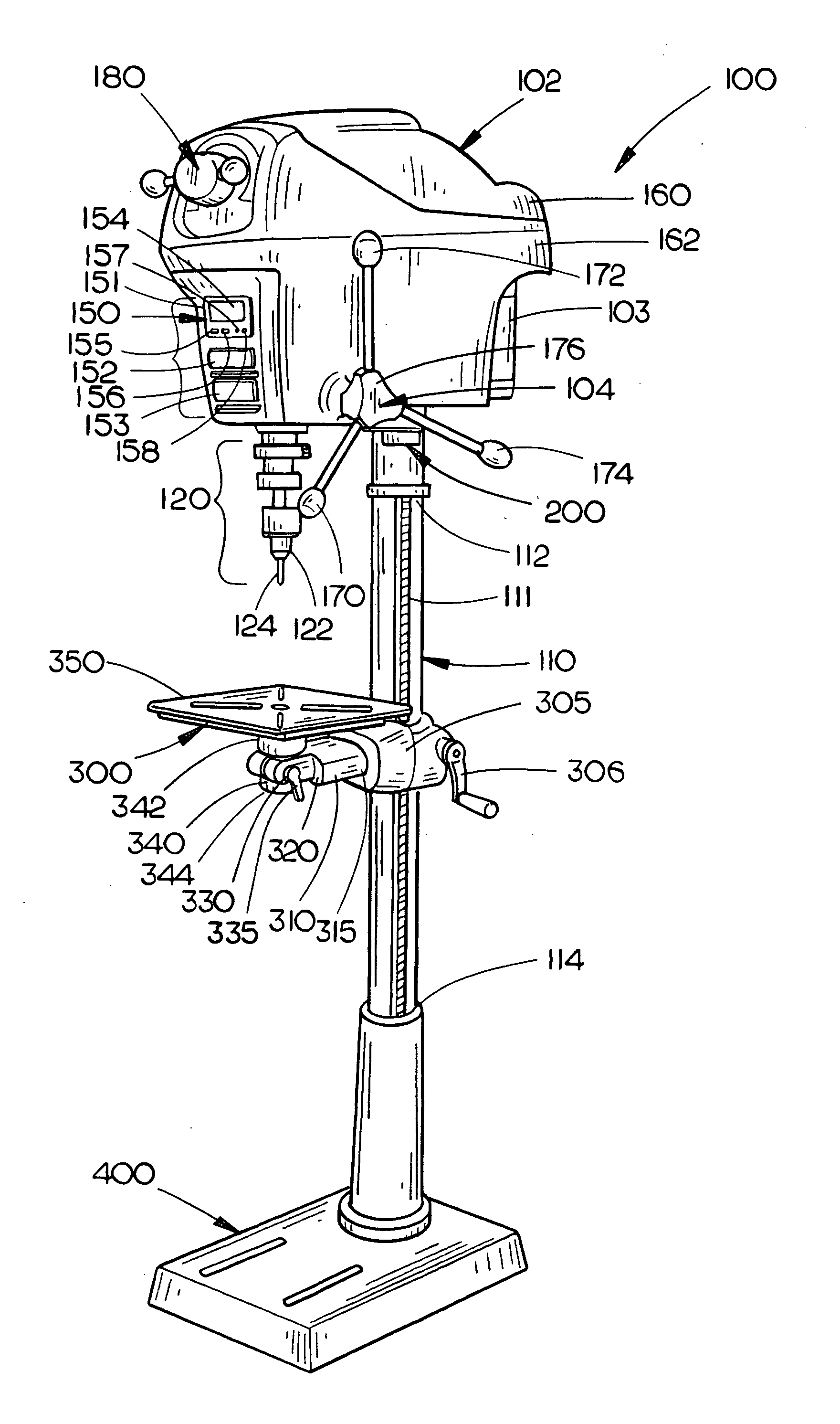
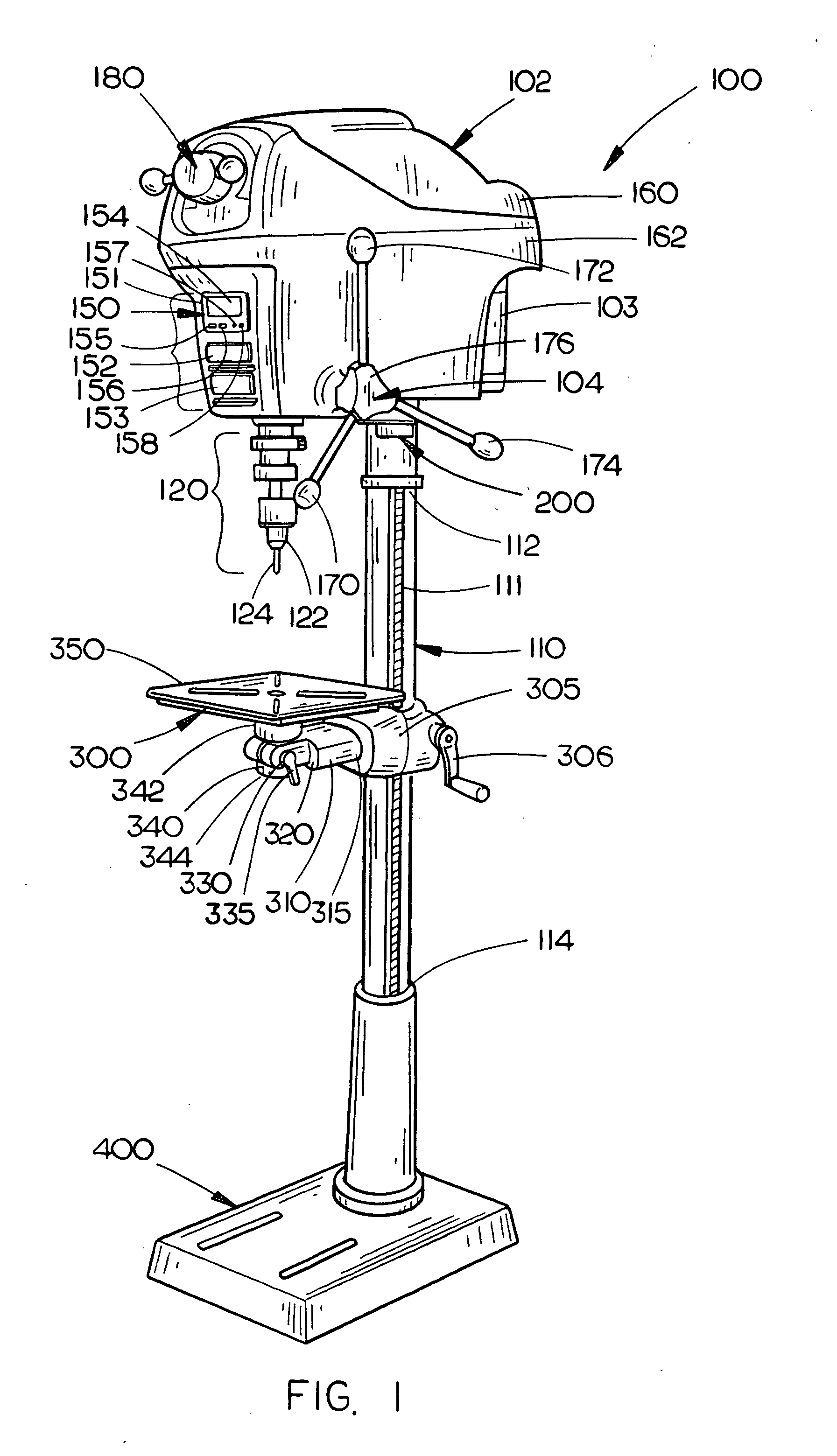
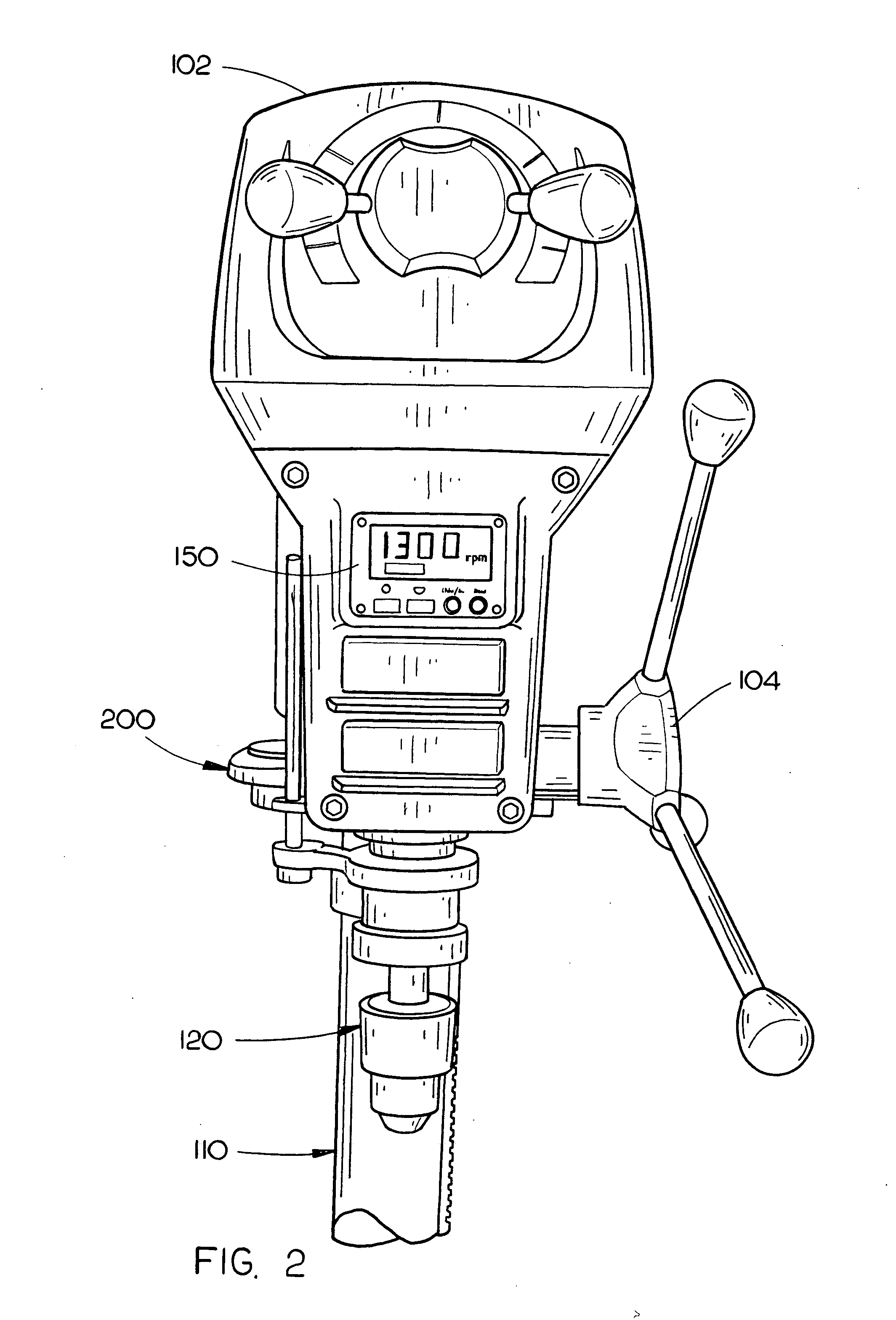
[0041] Reference will now be made in detail to the presently preferred embodiments of the invention, examples of which are illustrated in the accompanying drawings. 100141 Referring now to FIG. 1, a drill press 100 includes a head assembly 102 adjustably connected with a first end 112 of a bench column 110, the head assembly 102 at least partially encompassing a motor 103 operationally coupled with a quill assembly 120 which, through a spindle and chuck 122, couples with a drill bit 124. The quill assembly 120, through the drill bit 124, providing an axis of operation for the drill press 100. A crank mechanism 104 (feed handle assembly) is connected with the quill assembly 120 through the head casing 102. The crank mechanism 104 providing the user controlled “press” action for the drill bit 124. The bench column 110 is adjustably connected with a bench assembly 300 and connects with a stabilizing stand assembly 400 at a second end 114 of the bench column 110. A power tool control sy...


PUM

PropertyMeasurementUnit
Thicknessaaaaaaaaaa
Hardnessaaaaaaaaaa

Abstract

A power tool control system connected with a drill press provides a system for determining operational settings for the drill press and/or structural factors of a workpiece to be operated upon by the drill press. For instance, the power tool control system may establish a visual indication of the axis of operation of the drill press upon a workpiece and/or determine the thickness, structural composition, and/or moisture content of a workpiece. The determined axis of operation and/or structural factor is utilized to determine the operational settings of the power tool.

Description

CROSS REFERENCE TO RELATED APPLICATION [0001] The present application is a continuation-in-part of U.S. application Ser. No. 10 / 744,612, filed on Dec. 23, 2003, which is a continuation-in-part of U.S. application Ser. No. 10 / 632,559, filed on Jul. 31, 2003, which is a continuation of U.S. application Ser. No. 10 / 463,206, filed on Jun. 16, 2003 which is a continuation-in-part of U.S. application Ser. No. 10 / 445,290, filed on May 21, 2003, which claimed priority under 35 U.S.C. §119 to U.S. Provisional Application Ser. No. 60 / 429,840, filed on Nov. 27, 2002, and U.S. application Ser. No. 10 / 413,455, filed on Apr. 14, 2003 which claimed priority under 35 U.S.C. §119 to U.S. Provisional Application 60 / 414,200, filed on Sep. 27, 2002 and U.S. Provisional Application 60 / 373,752, filed on Apr. 18, 2002. The present application claims priority under 35 U.S.C. §119 to the U.S. Provisional Application Ser. No. 60 / 508,770, filed on Oct. 3, 2003, and the U.S. Provisional Application Ser. No. 60...

Claims


Application Information

Patent Timeline
IPC IPC(8): B23B49/00
CPCB23B39/00B23B45/006B23Q17/20B23Q17/24Y10T408/561Y10T408/50Y10T408/21Y10T408/5614Y10T408/99Y10T83/768Y10T83/741
Inventor ETTER, MARK A.BOYD, P. BRENTCARROLL, CRAIG A.STAFFORD, BRENTWESSEL, JEFFREY A.
Owner CHANG TYPE INDAL
Why Eureka
Try Eureka