Method and apparatus for pumping and diluting a sample

a sample and method technology, applied in the direction of positive displacement liquid engines, instruments, machines/engines, etc., can solve the problems of reducing the reliability of test results and subsequent test results, affecting the accuracy of sample measurement, etc., to achieve high precision dilution, accurate flow rate, and easy control

Inactive Publication Date: 2006-05-18
THERMO FISHER SCIENTIFIC INC
View PDF15 Cites 19 Cited by
  • Summary
  • Abstract
  • Description
  • Claims
  • Application Information

AI Technical Summary

Benefits of technology

[0031] A main advantage of the present invention broadly reside in a pumping or dilution system in which the sample is pumped to the analysis instrument at a flow rate determined by a highly accurate pump, without exposing that pump to the sample. This can reduce the likelihood of the pump becoming damaged or contaminated by the sample. Also, the accurate flow rate may be required for relatively high precision dilution of the sample.
[0032] Embodiments of the present invention also have the advantage of providing a pump / dilution system and method which is more easily controlled and to better accuracy levels of flow rate and dilution factor. Also, virtually no diluent is wasted during normal operation. A controller can advantageously be used to control the second and third pump flow rates. A dilution factor equal to the ratio of fourth to second flow rates can easily be controlled by adjusting the second and / or third pump flow rates accordingly. Control of the dilution factor can occur in substantially real time in response to data from the analysis equipment. Also, the components of the pump used to provide accurate, low level flow of the sample are not exposed to potentially damaging corrosive, chemical attack, or wear caused by suspended solids in the sample. Sample solution does not enter the second pump.
[0033] Embodiments of the invention have further advantages of substantially reducing the operator intervention, and increase the sample throughput rate. The embodiments aim to provide automated dilution of the sample at a consistent and safe level before the sample is introduced into the analyser. The rate of sample throughput can be substantially increased. Dilution of the sample to a safe level also has the advantage of allowing the required precision of analysis to be carried out on trace levels within the sample by automatic dilution of the sample. The sample throughput can also be increased by a relatively rapid introduction of new (or different) sample solutions up to the buffer by controlling the flow rate of the sample uptake. The cost of diluting samples can be reduced by reducing the amount of diluent used by the dilution system; only the volume of diluent required to dilute the sample to a required safe level can be consumed and little or no diluent is wasted. By ‘safe level’, we mean a dilution factor necessary to avoid contamination of the analysis instrumentation.

Problems solved by technology

Analysis equipment for analysing trace elements in liquids have a limited capability of measuring samples which have relatively high levels of dissolved solid material, or matrix (such as CaCO3 or dissolved salts in water, or the like).
Such high levels of matrix can have undesirable effects on the analytical equipment, for example, materials can be deposited on orifices, glassware and ion optical elements.
The dissolved solids can become deposited on components within the instrument, for example on the cones which sample the plasma and skim off a portion of the supersonic jet, thus significantly reducing the reliability of the test result and the results of any other subsequent test.
Such manual intervention is too cumbersome, time consuming and costly if many samples per day require analysis.
This requires considerable operator intervention.
Such a limit to the throughput of samples is undesirable and operator intervention is costly.
If the dilution is not maintained to a known level and within a relatively tight tolerance, the accuracy of the analysis results may be unacceptable.
Peristaltic pumps have a limited range of flow rates and the sample and diluent pumps often operate at the extremes of their flow rate range.
Also, the limited flow rate for peristaltic pumps limits the dilution factor by which the sample can be diluted; the maximum dilution occurring whilst the diluent pump operates at a maximum flow rate and the sample pump operates at a minimum flow rate.
If this rate is exceeded the instrument will become swamped with diluted sample which will cause problems in the spectrometer and have a detrimental effect on the analysis results.
Materials in the waste container are discarded and, since the high quality diluent necessary for accurate test results is relatively expensive, this wastage is an additional economic burden on test laboratories.
The inability to control the flow of diluent results in an uncontrolled dilution factor.
Problems arise with systems which rely on this arrangement.
For instance, there are limits to the dilution factor this system can provide, especially if the analyser requires the diluted sample to be pumped at a specific rate.
However, the problems associated with the system in FIG. 1 now become prevalent with the system, for example, diluent wastage.
Furthermore, contamination of the pump parts exposed to the sample during operation can cause subsequent samples to become contaminated, thus resulting in inaccurate analysis results.
This so called “memory effect” problem is particularly troublesome with highly sensitive analysis instruments.
As test instruments become more sensitive, this problem further increases.
(For example, we have found this problem has very little effect on analysis results when samples are tested using the relatively insensitive atomic absorption analysis instruments, but can be problematic when samples are tested using highly sensitive ICP-MS analysis tools).
Also, certain fluids can damage pump components.
Such damaged components can lead to inaccurate flow rates, or more seriously, render the pump unusable without lengthy repair or regular servicing.
However, peristaltic pumps have inadequate flow rate range and accuracy to dispense a sample solution at a sufficiently low flow rate to avoid discharging qualities of fluid to waste, as previously described.
Furthermore, the use of peristaltic pumps limits the dilution factor achievable, because of their limited effective flow rate range.

Method used


Image

  • Method and apparatus for pumping and diluting a sample
  • Method and apparatus for pumping and diluting a sample
  • Method and apparatus for pumping and diluting a sample

Examples


Embodiment Construction

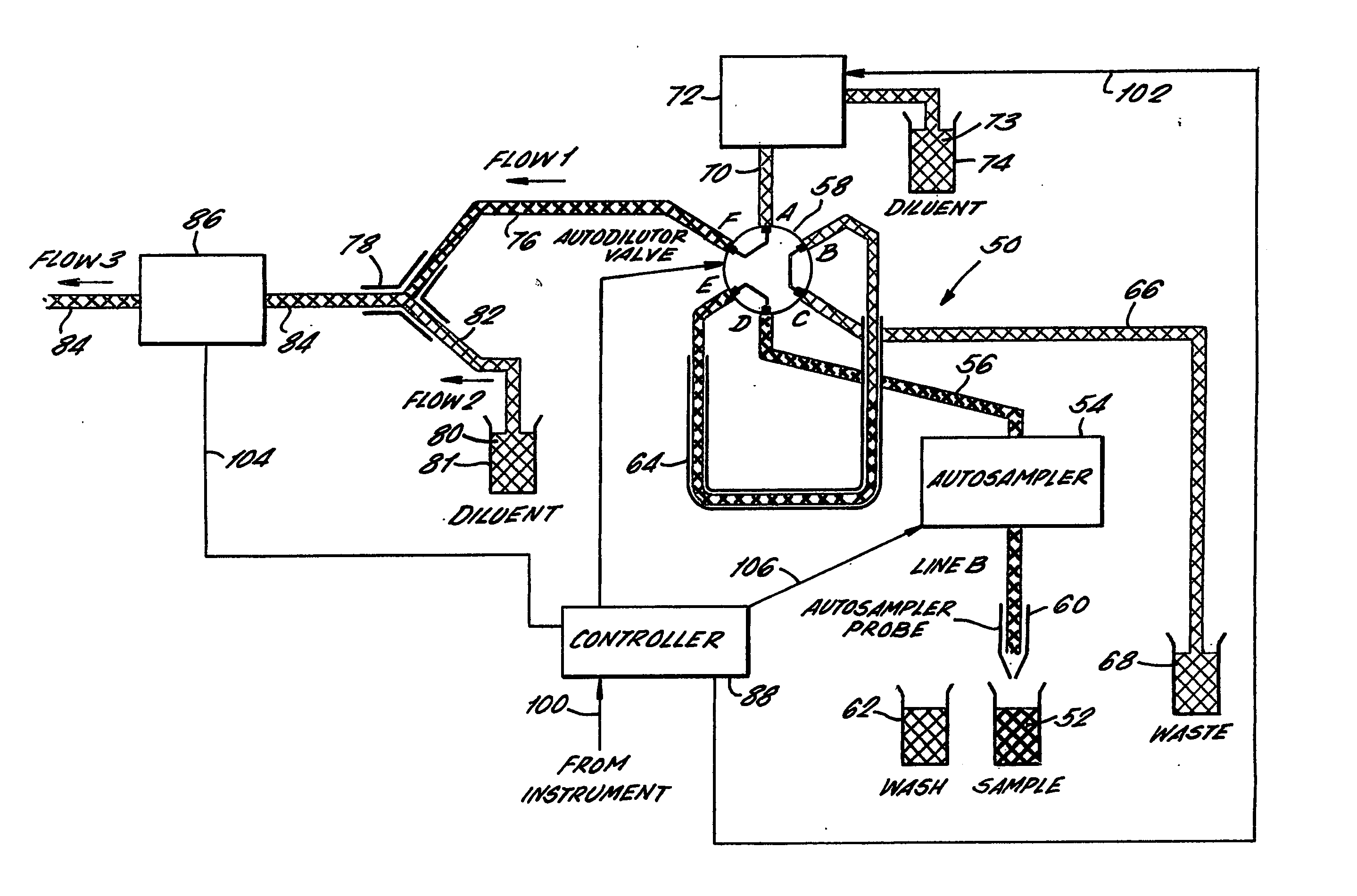
[0039] Referring to FIG. 3, a pump system 50 embodying the present invention is shown in schematic form. A sample 52 to be analysed is drawn from a container by an automatic sampler 54 along a first, or sample uptake pipe 56 to a valve, or pipe flow switch 58. The automatic sampler used in this embodiment is well known in the art and comprises a pump (not shown) and a probe 60. The probe is moveable to be inserted into a fluid in a container placed underneath the probe. Different containers can be placed on a carrousel (not shown) so that different samples or a washing agent 62 can be drawn into the pump system via the probe and automatic sampler pump.

[0040] The switch 58 comprises six input / output ports, A, B, C, D, E and F, and three internal pipes or conduits which each join one port with another. The switch is movable between two positions so that the flow of fluid from one pipe to another pipe can be switched from that pipe to a different pipe when the switch is moved. The swi...


PUM

PropertyMeasurementUnit
volumeaaaaaaaaaa
flow rateaaaaaaaaaa
flow ratesaaaaaaaaaa

Abstract

A pumping apparatus (50) which isolates a sample (52) from a pump (72), thereby circumventing the so-called “memory effect” problem. The sample is pumped into an intermediary, or buffer region (64) using a first pump (54). The sample is displaced from this buffer region by pumping a second fluid (74) into the buffer region using a second pump (72). When the sample is displaced from the buffer region it proceeds to a mixer (78) where it can be diluted before analysis. The second pump is required to operate with a high degree of accuracy so that the sample is diluted by a consistent amount. Preferably, the second pump is a highly accurate piston pump.

Description

PRIOR APPLICATIONS [0001] This application claims benefit of Patent Cooperation Treaty Application Number PCT / GB2003 / 003564, filed Aug. 14, 2003, which claims priority from Great Britain Application Number 0218949.6, filed Aug. 14, 2002.FIELD OF THE INVENTION [0002] This invention relates to a method and apparatus for pumping a sample to analysis equipment and diluting the sample before it is analysed, or for any other reason. [0003] The invention is described herein with reference to liquid samples which require dilution before they are analysed in a mass spectrometer. However, the invention is not limited to liquid samples or mass spectroscopy and can equally apply to dissolved or suspended samples and any other test or analysis equipment. DESCRIPTION OF THE RELATED ART [0004] Analysis equipment for analysing trace elements in liquids have a limited capability of measuring samples which have relatively high levels of dissolved solid material, or matrix (such as CaCO3 or dissolved ...

Claims


Application Information

Patent Timeline
Patent Type & Authority Applications(United States)
IPC IPC(8): F04B3/00F04B5/00G01N27/62G01N1/00G01N1/10G01N1/38G01N35/08
CPCG01N1/38G01N35/08G01N35/1097
Inventor SHAW, PHILIP NEILMARRIOTT, PHILIP
Owner THERMO FISHER SCIENTIFIC INC
Why Eureka
Try Eureka