Carbon filtration process and apparatus for removing PCB's and other compounds from wastewater

a carbon filter and wastewater technology, applied in the direction of chemistry apparatus and processes, multi-stage water/sewage treatment, sustainable biological treatment, etc., can solve the problem that the prefiltration before the granular activated carbon treatment provided minimal process benefits, and achieve the effect of saving millions of dollars in capital expenditures, cost-effectiveness, and saving an estimated $5 million in capital expenditures

Inactive Publication Date: 2006-05-25
HUBBELL ROTH & CLARK
View PDF6 Cites 9 Cited by
  • Summary
  • Abstract
  • Description
  • Claims
  • Application Information

AI Technical Summary

Benefits of technology

[0013] The second phase of the PCB studies was to evaluate the best effluent treatment method. One method for removing PCB is to use granular activated carbon. The pilot testing system consisted of two pressure filters in series: a sand prefilter followed by a granular activated carbon filter. The sand filter was used to remove suspended solids which were present in a plant's final effluent, to allow the carbon filter to work more efficiently. The study proved that PCB could be efficiently removed from the final effluent using granular activated carbon.
[0016] By not having to construct a sand prefiltering system prior to the activated carbon system, one municipality saved an estimated $5 million in capital expenditures.
[0017] The invention thus provides state of the art treatment for PCB. Direct carbon filtration of secondary effluent has proven to be cost-effective, providing an innovative treatment method that has saved millions of dollars in capital expenditures. This unique treatment system has improved the water environment which will help provide future redevelopment of a city that can be focused around both tourism and manufacturing.

Problems solved by technology

As a result of the PCB pilot test, it was determined that prefiltration before the granular activated carbon treatment provided minimal process benefits.

Method used


Image

  • Carbon filtration process and apparatus for removing PCB's and other compounds from wastewater
  • Carbon filtration process and apparatus for removing PCB's and other compounds from wastewater
  • Carbon filtration process and apparatus for removing PCB's and other compounds from wastewater

Examples


Embodiment Construction

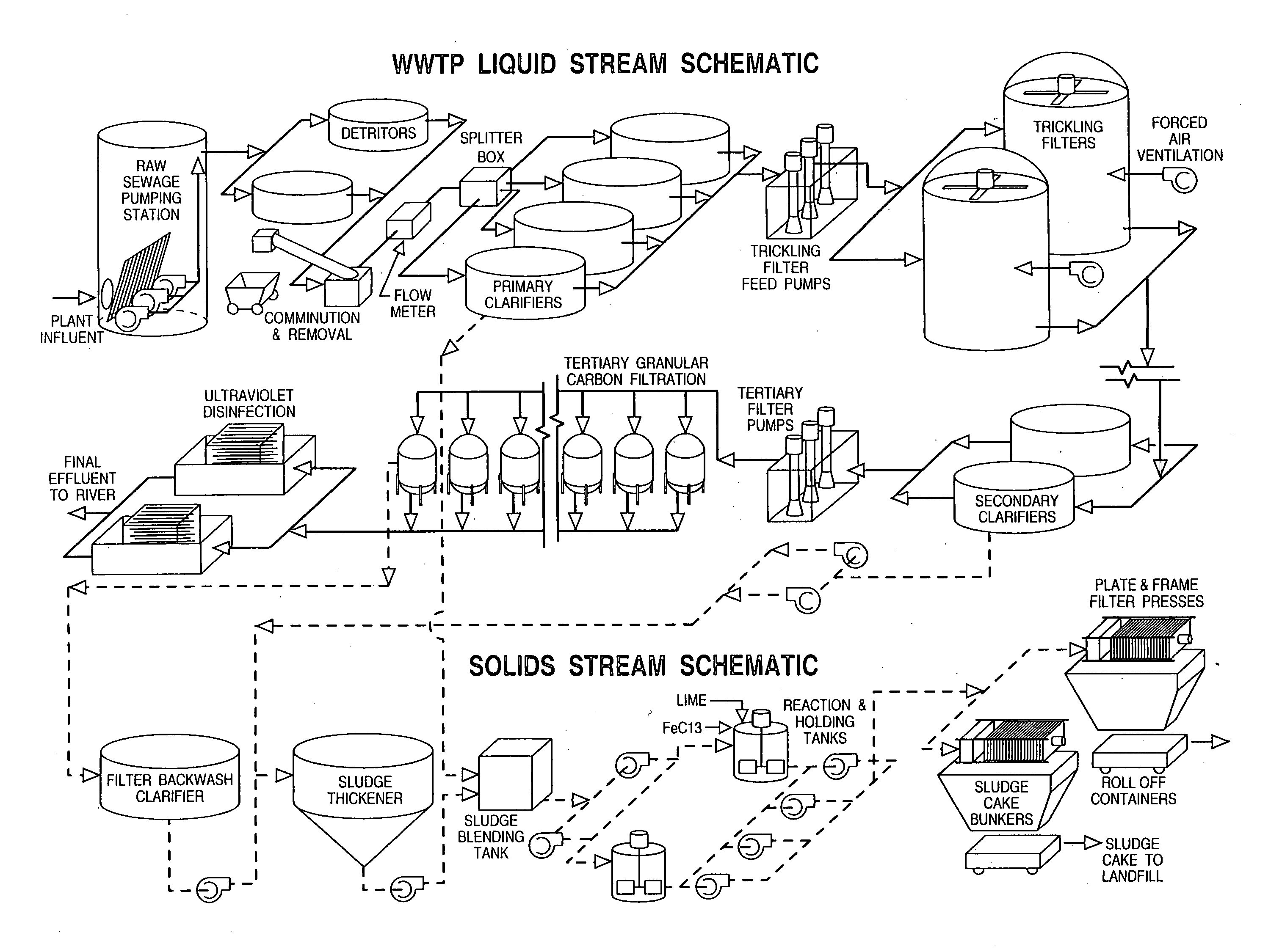
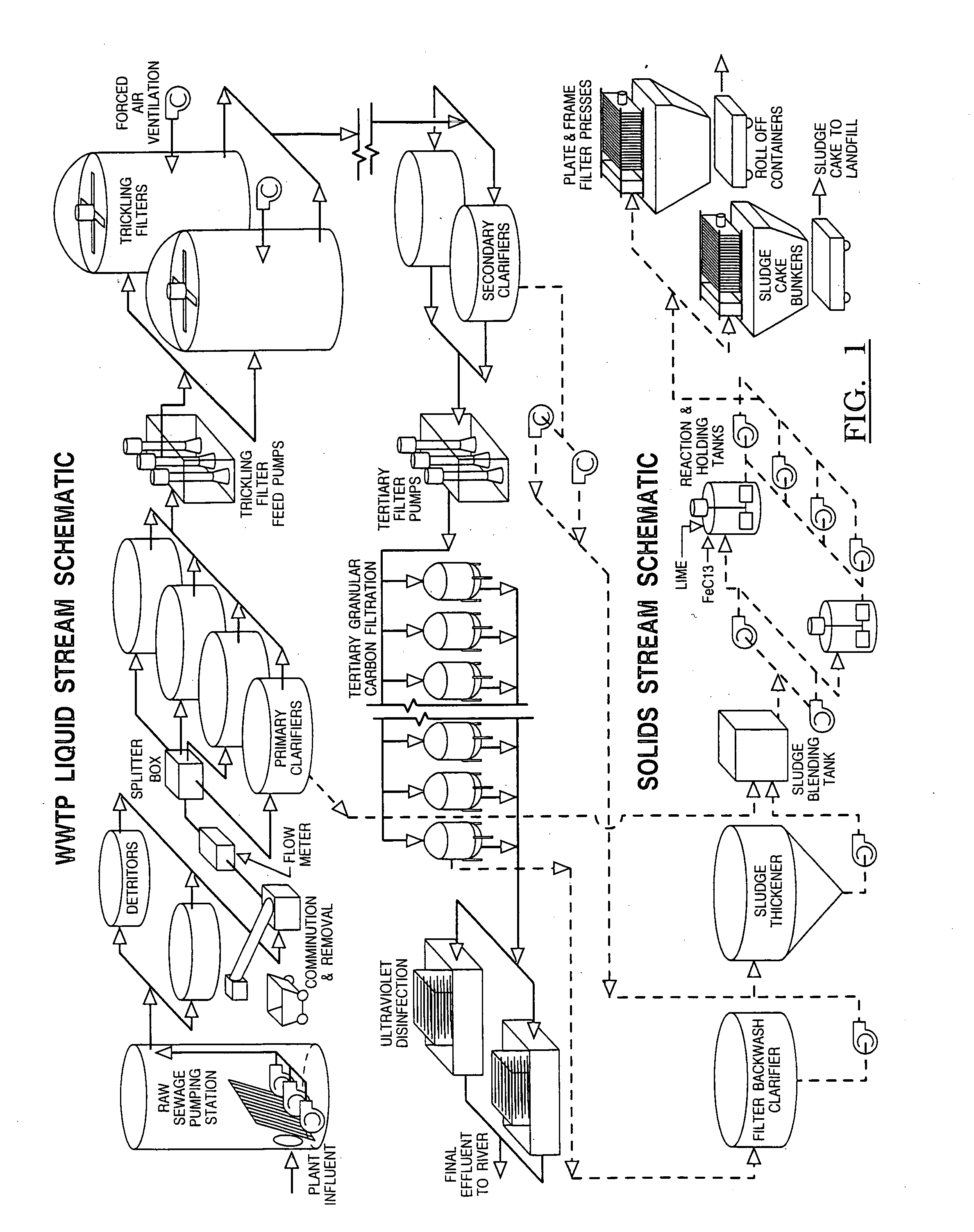
[0020] Referring now to FIGS. 1-2, sanitary sewage (influent) is transported to a wastewater treatment plant (WWTP) through a series of sewers, pumping stations, and interceptors to a raw sewage pumping station, located at the WWTP. In one embodiment of the invention, the raw sewage pumping station contains five pumps which lift the wastewater from deep in the sewer system up into the treatment plant where various unit processes are located to purify the wastewater.

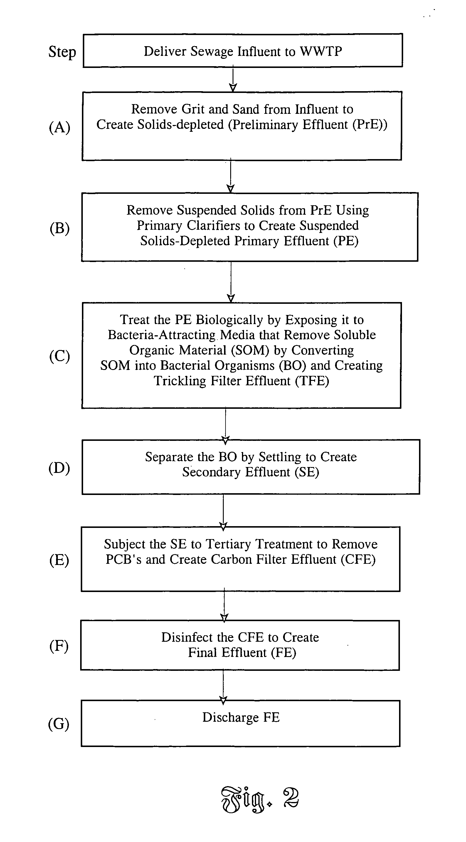
[0021] The first step (step A) in the treatment process involves removal of solids such as the sand and grit contained in the wastewater to create solids-depleted wastewater known as Preliminary Effluent (PrE) and thus protect downstream treatment plant systems from premature failure due to wear from the sand and grit. The solids are removed in tanks called detritors, where the sand and grit is allowed to settle out of the waste stream. Following sand and grit removal, the PrE continues to flow by gravity or pumping to o...


PUM

PropertyMeasurementUnit
diameteraaaaaaaaaa
pressureaaaaaaaaaa
volumeaaaaaaaaaa

Abstract

Process and apparatus for treating wastewater from a sewer system including the steps of: (A) removing solids contained in the influent to create solids-depleted preliminary effluent (PrE) and to protect downstream systems from premature failure due to wear from solid particles; (B) removing suspended solids from the PrE to produce a suspended solids-depleted primary effluent (PE); (C) treating the PE biologically by exposing it to bacteria-attracting media that removes soluble organic material, thereby creating trickling filter effluent (TFE); (D) separating the bacterial organisms by settling to create a secondary effluent (SE); (E) subjecting the SE to tertiary treatment to remove PCB's and other compounds and create a carbon filter effluent; (F) disinfecting the CFE to create a final effluent (FE); and (G) discharging the FE to a receiving environment.

Description

CROSS-REFERENCE TO RELATED APPLICATION [0001] This new utility application claims the benefit of provisional application Ser. No. 60 / 631,051, filed on Nov. 24, 2004.BACKGROUND OF THE INVENTION [0002] 1. Field of the Invention [0003] The invention relates to the process and construction of wastewater treatment plants. More specifically, the invention relates to a system for removing contaminants from wastewater. [0004] 2. Background Art [0005] Municipalities are often faced with the challenge of removing polychlorinated biphenyl (PCB) and other organic compounds from the discharge of their aging wastewater treatment facilities. Polychlorinated biphenyl is a man-made compound that was used in the manufacture of transformers, hydraulic oils, paints, and in other products. It has been determined to be a health risk to humans and is seen as a bio-accumulative chemical of concern. The PCB, which may be found in the plant's influent and sometimes in the effluent, must be removed to meet a ...

Claims


Application Information

Patent Timeline
Patent Type & Authority Applications(United States)
IPC IPC(8): C02F9/00C02F11/121C02F11/148
CPCC02F1/281C02F1/32C02F3/04C02F9/00C02F11/121C02F11/14C02F2001/007C02F2101/363Y02W10/10C02F11/148
Inventor CHRISTESON, CURT A.
Owner HUBBELL ROTH & CLARK
Why Eureka
Try Eureka