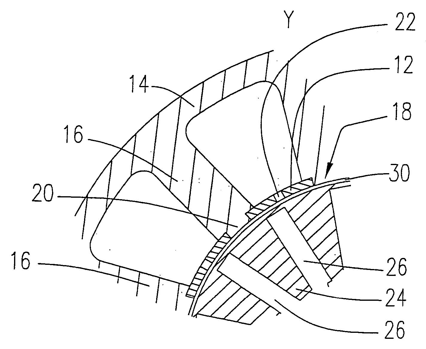
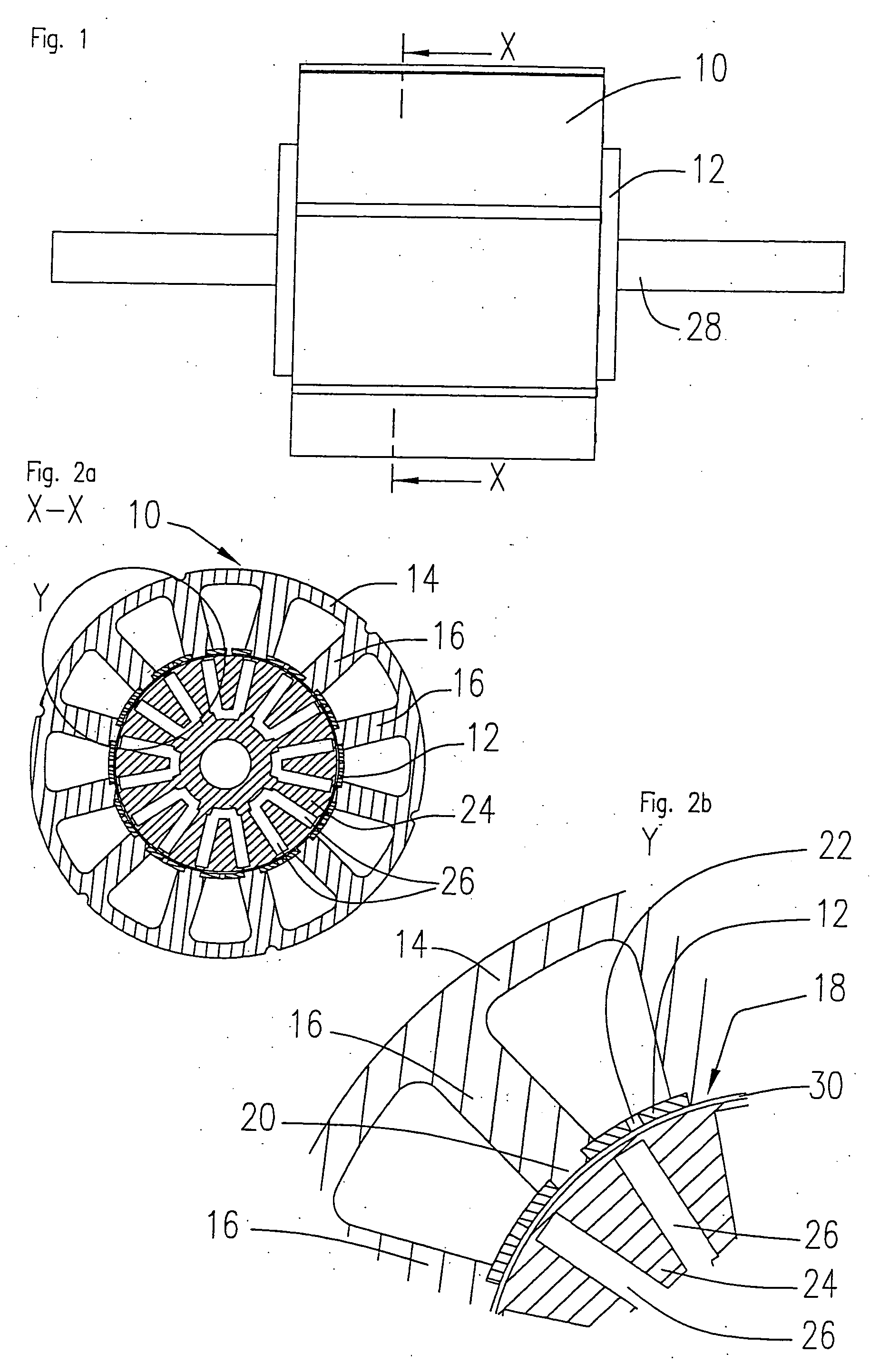
[0007] In the stator arrangement according to the invention, the sleeve takes on several functions. Firstly, it acts as a slot cover and holds the windings in the stator slots. For this function, it is expedient if the sleeve is given a
coating of an electrically insulating material on its surface facing the stator slots, so that it also takes on the function of insulating the slots. Another, more important function of the sleeve is to form pole shoes. To this effect, it is expedient if the sleeve is made of a ferromagnetic material and is magnetically coupled to the free ends of the stator teeth. Moreover, the sleeve is preferably designed in such a way that it has non-magnetic or low-magnetic zones between two adjoining stator teeth that extend in an axial direction in order to separate the pole shoes of adjoining stator teeth from one another. These zones between the pole shoes can be narrow since they merely have the function of magnetically isolating the pole shoes from one another. This provides a stator arrangement that has particularly wide pole shoes which is advantageous for the running performance of the
electric machine and, in particular, makes it also possible to reduce
cogging torque.
[0011] In a beneficial embodiment of the invention, the sleeve is also coated with an electrically insulating material on its surface facing away from the stator slots to provide electric insulation vis-à-vis the rotor, to prevent, for example,
voltage flash-over in case of failure.
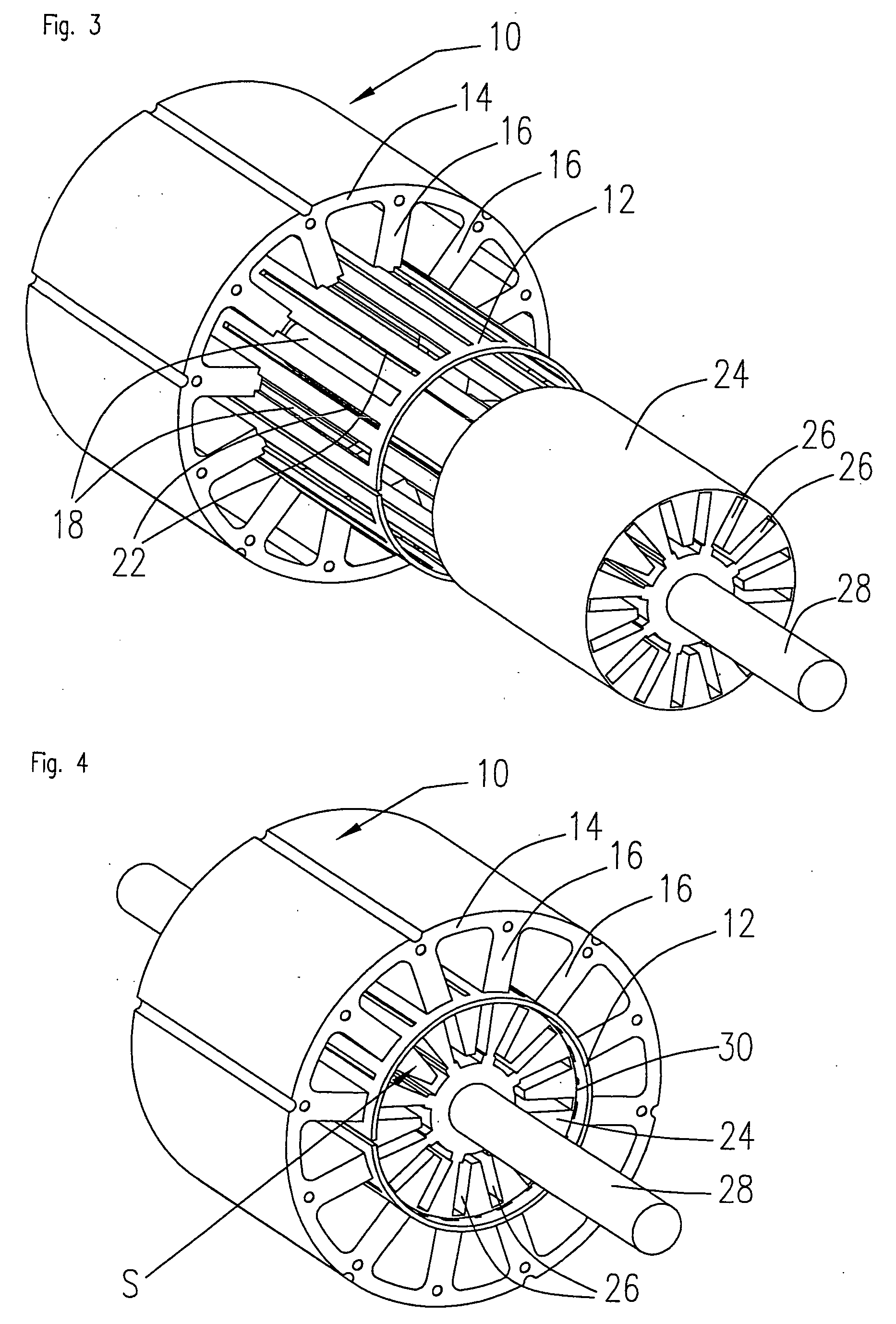
[0012] The stator arrangement according to the invention can be manufactured in a very simple and cost-effective process if the sleeve is made of stamped, rolled sheet
metal that can be coated if required. In the first embodiment, the sleeve is first die-
cut from flat sheet
metal, slits to separate the individual pole shoes and cutouts to connect the sleeve to the stator teeth being die-
cut at the same time. The sheet metal is then rolled to form a sleeve which is open at a joint and thus flexible. This makes it easier to
mount or press the sleeve onto the free ends of the stator teeth. It is expedient if the free ends of the stator teeth are given a fit that engages with the cutouts in the sleeve. A variety of different sleeve designs is conceivable. For instance, the cutouts to connect the sleeve to the stator teeth could take the form of slits that extend in an axial direction along the sleeve and which are closed at both axial ends of the sleeve. In this embodiment, the cutouts are pressed onto the stator teeth. In an alternative embodiment, the cutouts are formed by slits that are only closed at one axial end of the sleeve. In this embodiment, the sleeve can be slid onto the stator body or the stator teeth respectively, in an axial direction. In another embodiment of the invention, lateral slits are formed in the stator teeth close to their free ends allowing the sleeve to be slid onto the stator teeth in an axial direction such that the edges of the cutouts engage in the slits. This has the
advantage that the sleeve cannot be pulled off the
stator poles as a result of the magnetic attraction of the
rotor magnets. In addition or as an alternative, the sleeve can also be fixedly connected to the stator teeth by means, for example, of
welding, particularly
laser welding, or bonding. To give the sleeve greater stability, it could be practical to seal the joint of the rolled sleeve after it has been mounted onto the stator body. An open joint has the
advantage that greater tolerances can be allowed when the sleeve is die-
cut and that the sleeve is more flexible.
[0014] In its second embodiment, the sleeve is die-cut from flat sheet metal in a similar way as in the first embodiment, the sheet metal being made of a bi-permeable material of the kind described above. Cutouts to connect the sleeve to the stator teeth are die-cut at the same time, but slits to separate the individual poles of the stator are not required. The sheet metal is then rolled to form a sleeve which is open at a joint and thus flexible. The sleeve can be slid onto the stator teeth in an axial direction or pressed onto the stator teeth. Before or after the sleeve has been mounted onto the stator teeth, preferably before the sheet metal is rolled to form a sleeve, the sleeve is locally heated within the zones that extend in an axial direction and lie between two adjacent stator teeth in order to transform the bi-permeable material within these defined zones from its original ferromagnetic state to a paramagnetic state. To this effect, the zones are preferably heated to a temperature >1150° C. using, for example,
laser or
induction welding. Although this second embodiment requires the additional process of locally heating the sleeve, it has the
advantage of providing a sleeve with improved
mechanical stability compared to the slotted sleeve. Magnetic short circuits in the region of the end face of the sleeve, where the slits of the first embodiment are bridged, can be avoided.
[0016] Practical trials using the stator arrangement according to the invention have shown that the sleeve generates a certain proportion of eddy currents, these effects being lesser in the embodiment having the slits than in the embodiment in which the sleeve is made of the bi-permeable material. The problem of
eddy current formation can be minimized by building up the sleeve from individual
layers that are electrically insulated with respect to each other in a similar way as used in the production of a stator body from a stamped lamination stack. To this effect, it is preferable if a series of laminations made of a ferromagnetic material or of the bi-permeable material is stacked and die-cut into narrow
metal strips. The laminations are then joined together. If the laminations are made from the bi-permeable material, it is best if the laminations are transformed into a paramagnetic state in the region of the zones by heating, using, for example,
laser or
induction welding, and simultaneously connected together within this region. Then the cutouts to slide the sleeve onto the stator teeth are cut out, die-cut for example, and the sleeve is rolled and joined together at its ends, if required. The advantage of this arrangement is that, due to the laminated structure, eddy currents within the sleeve material are almost totally avoided.
[0017] In a particularly preferred embodiment of the invention, at least one axial end of the sleeve projects beyond the end face of the stator body in an axial direction. This embodiment has the advantage that the bridges disposed at the axial end faces that hold the sleeve together and bridge the pole shoes, can be disposed beyond the
magnetic field of the rotor. This prevents the sleeve from forming a magnetic
short circuit in the region of the rotor. Another advantage of a sleeve that projects beyond at least one end face of the stator body in an axial direction is that it shields the stator magnetic fields towards the rotor. This makes particular sense for those machines in which a magnetic sensor to measure the rotational position is mounted opposite the end face of the rotor on the stator or on the
flange. The
shielding effect of the axially protruding sleeve means that these magnetic sensors are not influenced by the
magnetic field of the stator and can thus determine the rotational position of the rotor more accurately.

