
Method and apparatus for eddy current-based quality inspection of dry electrode structure

a dry electrode and quality inspection technology, applied in the direction of instruments, sorting, measurement devices, etc., can solve the problems of rejects, inability to provide adequate quality control for dry electrode units, and inability to inspect the outer surfa

Inactive Publication Date: 2006-05-25
ENERIZE CORP
View PDF3 Cites 23 Cited by
  • Summary
  • Abstract
  • Description
  • Claims
  • Application Information

AI Technical Summary

Benefits of technology

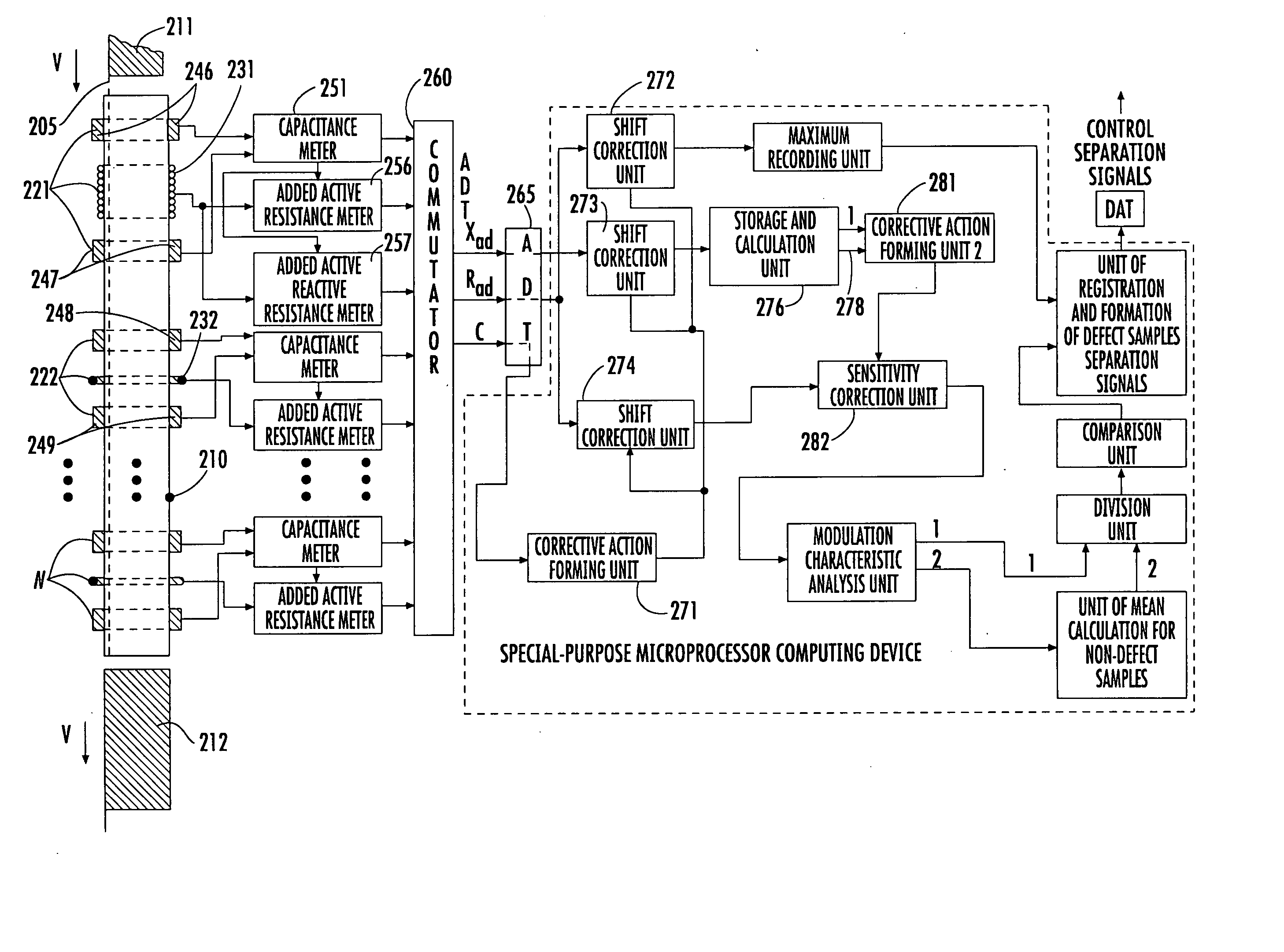
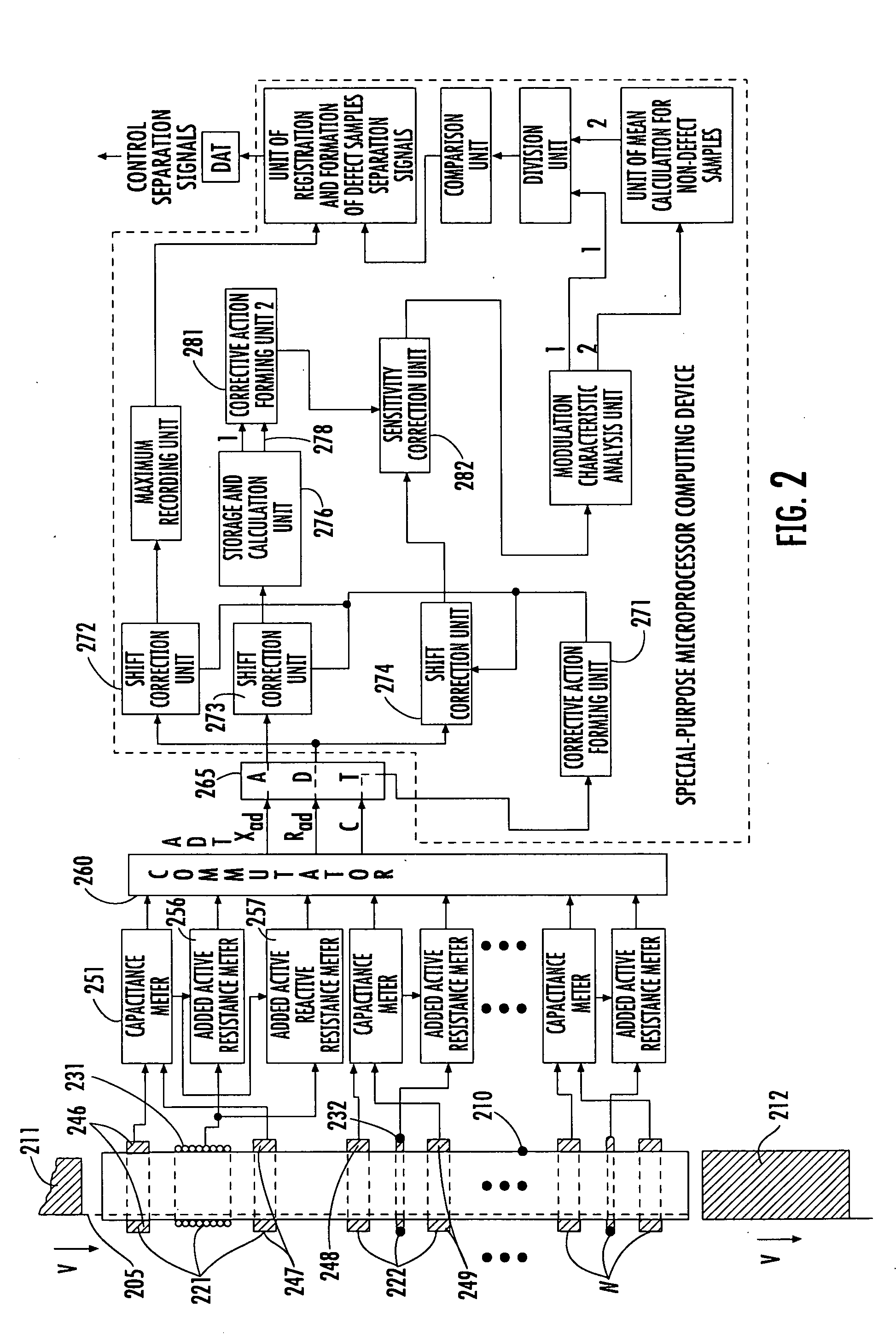
"The invention is a method and system for inspecting the quality of dry electrode units of energy storage devices, such as batteries, supercapacitors, and fuel cells, using an eddy current-based inspection system. The system includes a conveyor belt and a hollow dielectric shell with measuring transducers that induce eddy currents in the electrode unit. The impedance of the electrode unit is measured at multiple frequencies, and the modulation characteristics of impedance are used to determine if the electrode unit is defective. The system also includes strap capacitors that correct errors in the impedance data caused by shifting movement of the conveyor belt. The method and system provide a non-destructive and non-contact way to inspect the quality of dry electrode units."

Problems solved by technology

Experience proves that even when the physico-chemical characteristics of the initial raw material components vary within a tolerable range, overall discrepancies may lead to the appearance of rejects.
Therefore stabilization of the operating conditions when producing the structural components, and of their physico-chemical characteristics alone cannot provide adequate quality control for dry electrode units.
Any outer visual inspection is also not possible as the unit components are inaccessible.
Opening of the coiled electrode structures for visual inspection is not viable since the active mass of electrodes for example the carbon, lithium-treated cobalt oxide, etc., deposited onto a current collector for example copper or aluminum electrode strip features high brittleness, and fractures during repeated deformations.

Method used


Image

  • Method and apparatus for eddy current-based quality inspection of dry electrode structure
  • Method and apparatus for eddy current-based quality inspection of dry electrode structure
  • Method and apparatus for eddy current-based quality inspection of dry electrode structure

Examples


example 1

[0102] This Example shows the results of studying samples of dry electrode units of lithium-ion batteries. In all 12 units were studied (the units were numbered from 1 to 13 excluding number 3 that was disassembled).

[0103] To study the resistance to defects of the anode and cathode coats of the units they were subjected to compression in a press at various loads at the vendor site. The loads are given in Table 1.

[0104] The electrode unit samples No. 1, 11, 12, 13 were not subjected to loads.

TABLE 1No. of unit1245678910111213Load,02507501000125015002000500010000000kg

[0105] By visual inspection it was found that samples No. 8 and 10 have a closed outer layer of foil, while in sample No. 10 this layer was partially destroyed and the contact area was less.

[0106] Five (5) eddy current probes were used for studying the samples of the electrode units. The first of them contained W=6 turns of copper wire with a diameter d0=1 mm, densely wound. The operating frequency of this probe was ...

example 2

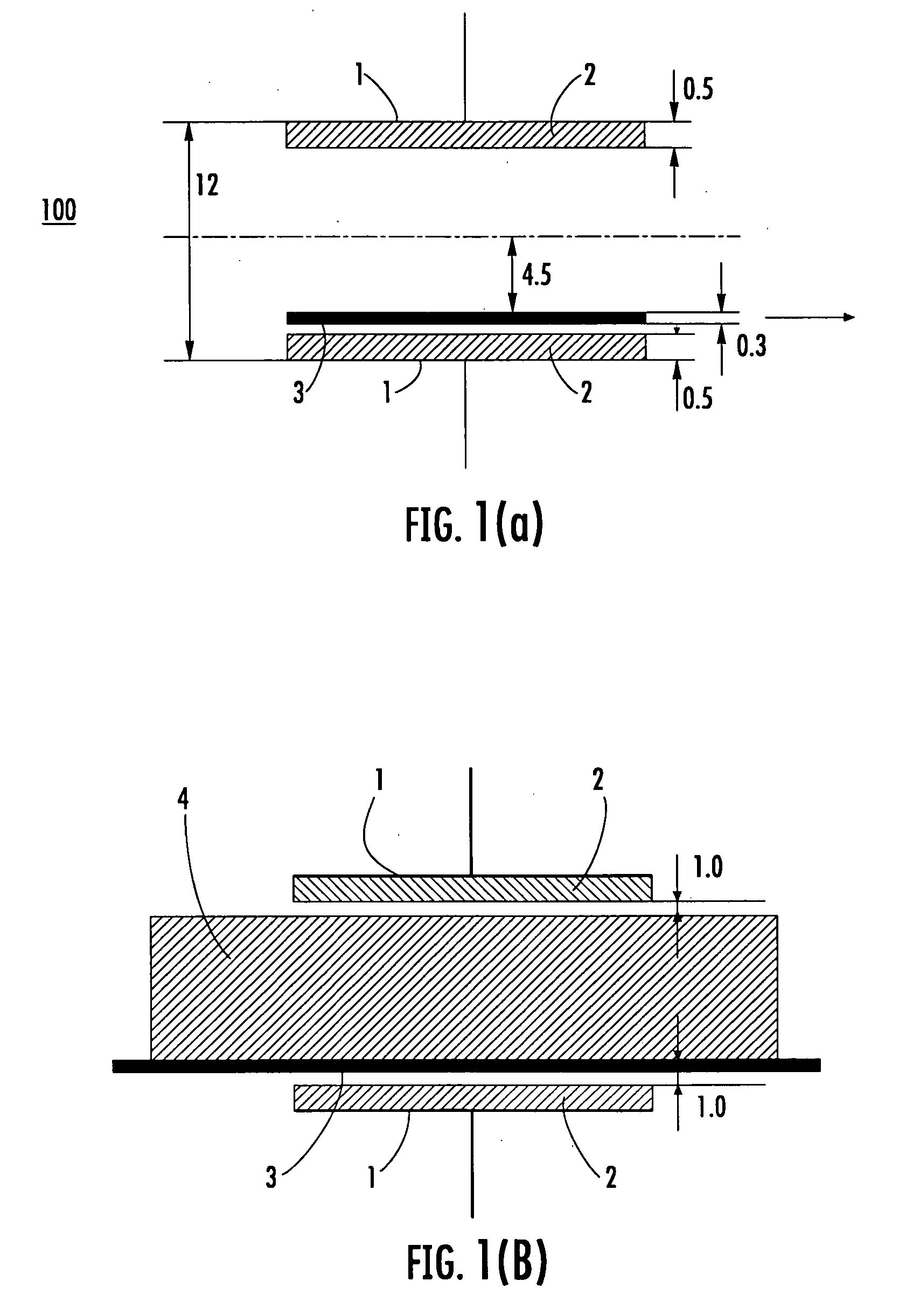
[0115] This Example contains an approximate calculation of the initial capacitance of the capacitor whose plates are placed on a dielectric shell surrounding the conveyor belt. The shape and the dimensions of the shell correspond to the electrode units the results of whose studies are discussed in Example 1. The 5 mm wide plates are placed in the slot of the shell so that the wall thickness of the shell in the place where the plate is arranged equals 5 mm.

[0116] Taking into regard the shape of the shell that in its perpendicular section is similar to the shape of a cylindrical jelly roll electrode unit, it can be accepted in the first approximation that the capacitor plates are plane while the capacitor is plane-parallel (see FIG. 1(a)).

[0117] Such a capacitor can be replaced with a chain of five connected in series capacitors (C1, C2, C3, C4, C5). Here C1=C5 is the capacitance of the dielectric wall of the shell in the place where the plates are located; C2 is the capacitance of ...

example 3

[0126] This example contains the calculation of the intensity components of the magnetic field of a turn under current for determining the distance between the turn of the eddy current probe and the capacitor plate.

[0127] The mutual position of the turn and the plates is schematically shown in FIG. 10. The expressions of the intensity components of the magnetic field of circular current has the following form: Hα=0Hρ=I2⁢ ⁢π⁢ ⁢ρ·z[(R+ρ)2+z2]1 / 2[-K+R2+ρ2+z2(R-ρ)2+z2⁢N];Hz=I2⁢ ⁢π·1[(R+ρ)2+z2]1 / 2[K+R2-ρ2-z2(R-ρ)2+z2⁢N].(10)

[0128] Here R is the turn radius, K and N are the full elliptic integrals of the first and second type. The approximate expressions (in series form) for these integrals are given below. 2π⁢K=1+2⁢ ⁢k28+9⁢(k28)2+50⁢(k28)3+12254⁢(k28)4+…⁢ ,(11)2π⁢N=1-2⁢k28-3⁢(k28)2-10⁢(k28)3-1754⁢(k28)4+…⁢ ,(12)where⁢ ⁢k2=4⁢ ⁢ρ⁢ ⁢R(R+ρ)2+z2. 

[0129] The corresponding intensity values Hρ and Hz on the line ρ=R (see FIG. 10) are now calculated. On this line the intensity components can b...


PUM

PropertyMeasurementUnit
thicknessaaaaaaaaaa
frequencyaaaaaaaaaa
frequencyaaaaaaaaaa

Abstract

A system for non-destructive non-contact quality inspection of dry electrode units of energy storage includes an eddy current-based inspection system having a conveyor belt, and a hollow dielectric shell. An outer surface of the shell has a plurality of spaced apart measuring transducers. Each of the transducers include a feed-through eddy current probe and at least two strap capacitors spatially linked therewith. In the related method, an electrode unit to be inspected is placed on the conveyor belt and enters and moves through the dielectric shell. The electrode unit is excited using a magnetic field from the eddy current probe as it passes by each of the plurality of transducers, where eddy currents at a plurality of frequencies are induced in the electrode unit. The modulation characteristics of impedance at a plurality of frequencies are measured by the probes, and from the impedance data it is determined whether the electrode unit is defective.

Description

CROSS-REFERENCE TO RELATED APPLICATIONS [0001] This application incorporates by reference in its entirety and claims priority to Provisional Application No. 60 / 616,440 entitled “METHOD AND APPARATUS FOR NONDESTRUCTIVE NONCONTACT QUALITY INSPECTION OF DRY ELECTRODE STRUCTURE OF ENERGY STORAGE” which was filed on Oct. 6, 2004.BACKGROUND OF THE INVENTION [0002] 1. Field of Invention [0003] The invention relates to methods and apparatus for electromagnetic-based quality inspection of energy storage, for example batteries, supercapacitors, and fuel cells. [0004] 2. Description of the Related Art [0005] The operating ability of chemical power sources is substantially determined by the quality of its structural components including cathode, separator, and anode. Inspection to monitor the quality of these structures allows removal of defective units which prevents use of faulty electrode units in the downstream technological component assembly operations, thus reducing system defects due to...

Claims


Application Information

Patent Timeline
Patent Type & Authority Applications(United States)
IPC IPC(8): G01N27/82
CPCG01N27/9026G01N27/904G01N27/9046G01R31/3627G01R31/385G01N27/82G01N27/90
Inventor REDKO, VOLODYMYRKHANDETSKYY, VOLODYMYRNOVAK, PETERSHEMBEL, ELENAKOHARA, SATOSHI
Owner ENERIZE CORP
Learn More