Fiber waveguide optical subassembly module

a fiber waveguide and optical sub-assembly technology, applied in the field of optical sub-assembly, can solve the problems of power output and transmission quality being turned down, misalignment and poor coupling, and the laser diode alignment is difficult to achieve, and achieves the effect of reducing dispersion, increasing alignment tolerance, and reducing cos

Inactive Publication Date: 2006-05-25
IND TECH RES INST
View PDF11 Cites 4 Cited by
  • Summary
  • Abstract
  • Description
  • Claims
  • Application Information

AI Technical Summary

Benefits of technology

[0008] The object of the invention is to provide a fiber waveguide optical subassembly to increase the alignment tolerance between the active optical element and the waveguide. The filter is thinner to lower the dispersion caused by the optical coupling gap. It reduces the cost and enhances the transmission rate.

Problems solved by technology

In the emitter side, there are alignment problems between the laser diode and the single-mode fiber or planar waveguide.
Because the alignment tolerance of a single-mode fiber or planar waveguide is just 1 or 2 microns, it is easy to be misaligned and poor coupling, and the power output and quality of transmission is turned down.
It can achieve precise alignment, however it costs much.
It greatly saves assembly cost, however the process is difficult to be approached.
Because the laser beam transmitting in a free space diffuses in accordance with its transmission distance, it encounters a problem that the final laser beam coupled to the single-mode fiber is less.
However, using micro lens increases the cost and the complication of assembly.
The three interfaces all encounter problems of optical misalignment.
Different types of waveguide further have problems of field mismatch.
Therefore, it is hard to improve the coupling efficiency of the whole unit.
However, the coupling efficiency is still low and the lens increases the cost.
The tubular light emitter and tubular light receiver increase the cost of the optical components.
Further, the tubular components have larger dimensions that increase the coupling length in free space and cause lower efficiency and light dispersion in the transmission.
As described above, whatever for a planar waveguide optical subassembly or a tubular optical subassembly, the cost of the assembly in the coupling interface is hard to be reduced.

Method used


Image

  • Fiber waveguide optical subassembly module
  • Fiber waveguide optical subassembly module
  • Fiber waveguide optical subassembly module

Examples


second embodiment

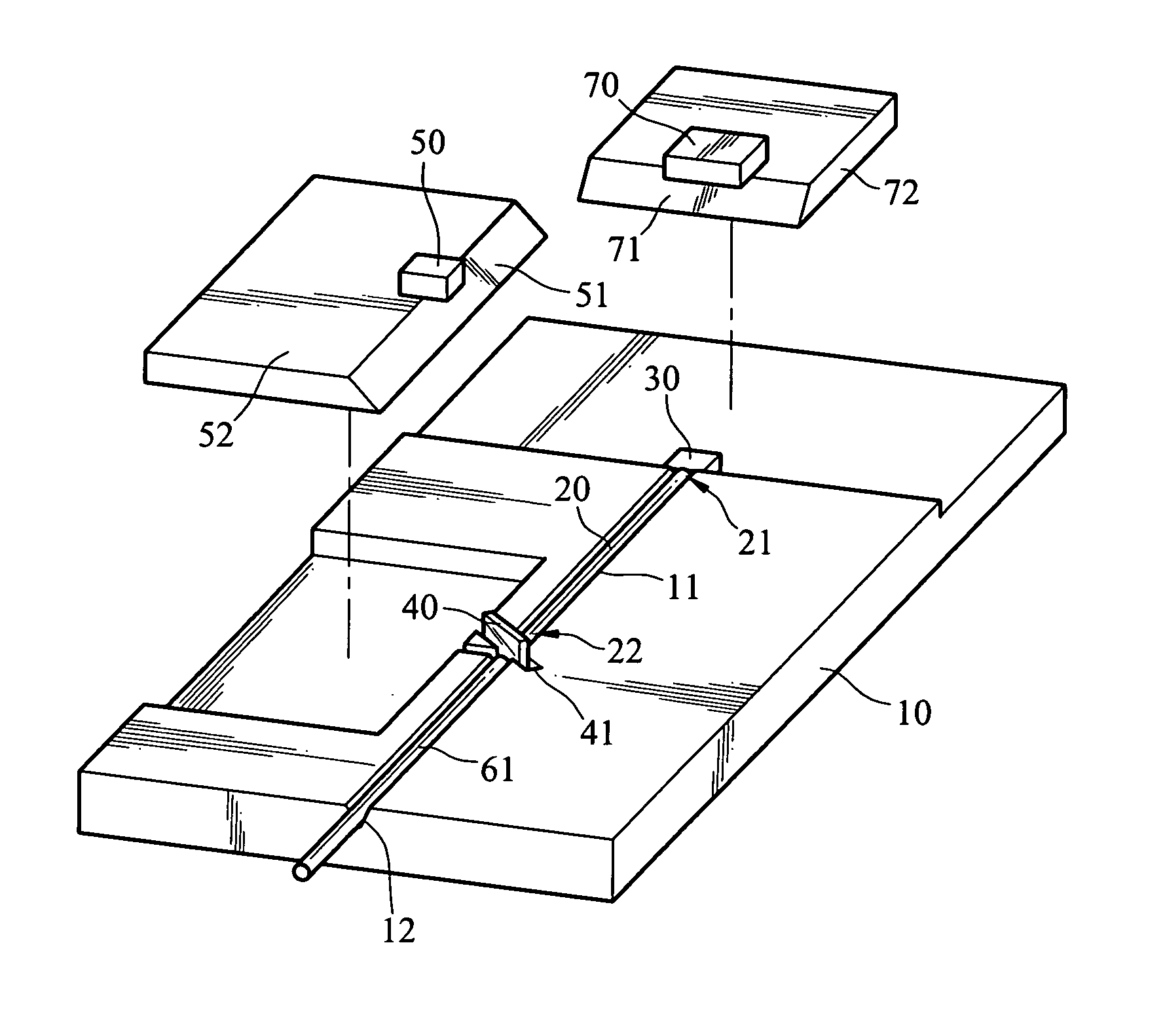
[0024] To prevent from difficulties of fabricating the reflective surfaces 51, 71 on the optical bench 10, a second embodiment is provided as shown in FIG. 3A and FIG. 3B. A monitor carrier 72 formed with a reflective surface 71 carries the monitor 70. The same, a detector carrier 52 formed with a reflective surface 51 carries the light detector 50. Therefore, the optical bench 10 is not needed for being machined with the reflective surfaces 51, 71; but only to be mounted with the monitor carrier 72 and the detector carrier 52.

first embodiment

[0025] On the other hand, the invention may further comprise a third optical transmission element. The third optical transmission element is a multi-mode optical fiber described below, of course the third optical transmission element may is a planar waveguide. triplexer optical subassembly of the invention is shown in FIG. 4. It has a similar construction to the duplexer optical subassembly described above, but further having a second multi-mode optical fiber 62 located in a fiber groove 13; and a third splitter 42 located in a third splitter groove 43. The second multi-mode optical fiber 62 has a front end 621 coupled with the splitter 40; and a rear end 622 coupled with the third splitter 42. In the drawing, besides the fiber groove 13 and the third splitter groove 43, other optical components, such as the emitter groove 31, the splitter groove 41, the light detector 50, a third light detector 80 and monitor 70, are applied in the same way.

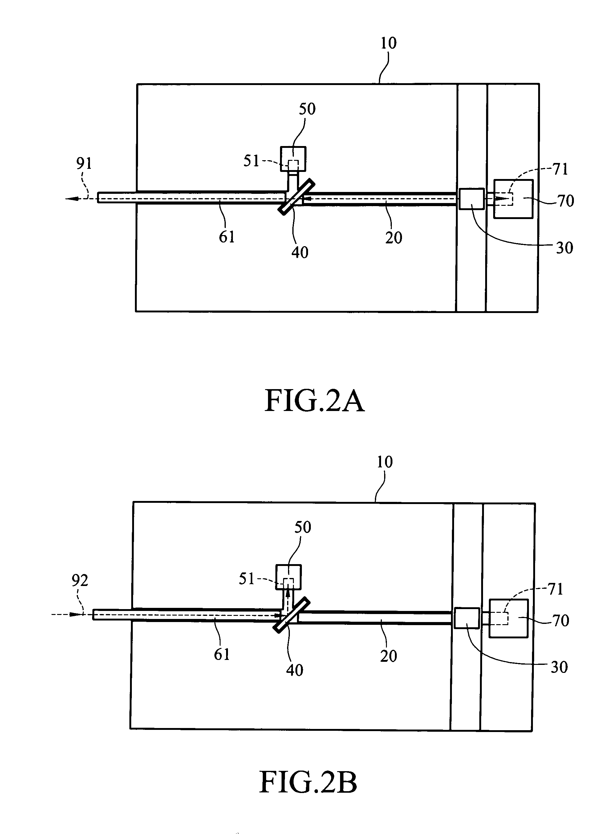
[0026] As shown in FIG. 5A, the output li...


PUM


Abstract

A fiber waveguide optical subassembly uses the multi-mode fiber to increase the alignment tolerance between the active optical element and the waveguide. The filter is thinner to lower the dispersion due to the optical coupling gap. The subassembly further combines the optical bench to achieve passive positioning. Therefore it reduces the cost and enhances the transmission rate.

Description

FIELD OF THE INVENTION [0001] The invention generally relates to an optical subassembly applicable to passive optical network (PON) and fiber-to-the-home (FTTH) systems, and in particular relates to a fiber waveguide optical subassembly. BACKGROUND OF THE INVENTION [0002] The bi-directional optical transceiver commonly used in passive optical network (PON) and fiber-to-the-home (FTTH) systems are mainly of two types, duplexer and triplexer. The duplexer processes both data and voice signals, while the triplexer processes data, voice and video signals. As the increasing demands of digital and analog video transmission, conventional duplexer cannot meet the market requirements, and triplexer becomes the trend of optical communication in the future. [0003] A duplexer optical subassembly mainly includes a light emitter and a light receiver. The light emitter is mainly a laser diode; the light receiver is mainly a photo diode. Whatever an emitter or a receiver, the optical path requires ...

Claims


Application Information

Patent Timeline
Patent Type & Authority Applications(United States)
IPC IPC(8): G02B6/36
CPCG02B6/4246
Inventor TSAI, MING-LANGCHOU, MING-JIETSAI, BOR-CHENWU, ZONG-YUANKO, CHIH-HSIANGCHANG, CHIN-SHENGCHIOU, YII-TAYCHU, CHUN-HSUNCHEN, JUNG-TAI
Owner IND TECH RES INST
Why Eureka
Try Eureka