Pattern for the surface of a turbine shroud

a turbine shroud and surface technology, applied in the direction of machines/engines, stators, liquid fuel engines, etc., can solve the problems of reducing the overall efficiency of the gas turbine engine, and easily exceeding the acceptable temperature limit, so as to improve the aerodynamic performance of the turbin

Active Publication Date: 2006-05-25
GENERAL ELECTRIC CO
View PDF7 Cites 57 Cited by
  • Summary
  • Abstract
  • Description
  • Claims
  • Application Information

AI Technical Summary

Benefits of technology

[0012] Exemplary embodiments of the invention include a pattern for improving aerodynamic performance of a turbine including a material disposed at a base surface disposed at an interior surface of a turbine shroud such that the material is capable of abradable contact with a tip portion of a turbine bucket. The material is disposed in a pattern including a first plurality of ridges disposed at the base surface such that at least a first portion of the first plurality of ridges corresponding to at least a back portion of the turbine bucket is oriented at a first angle with respect to an axis of rotation of the turbine bucket. Each ridge of the first plurality of ridges has a first sidewall and a second sidewall. The first and second sidewalls each have a first end and an opposite second end. The first end of the first and second sidewalls extends from the base surface. The first and second sidewalls slope toward each other until meeting at the second ends of respective first and second sidewalls defining a centerline and a top portion of the ridge. The first and second sidewalls are inclined with substantially equal but opposite slopes with respect to the base surface.

Problems solved by technology

As the gases leave the combustor, the temperature can easily exceed the acceptable temperature limitations for the materials used in construction of the nozzles and buckets in the turbine.
The high temperature in early stages of the turbine creates a variety of problems relating to the integrity, metallurgy and life expectancy of components coming in contact with the hot gas, such as the rotating buckets and turbine shroud.
Although high combustion temperatures normally are desirable for a more efficient engine, the high gas temperatures may require that air be taken away from the compressor to cool the turbine parts, which tends to reduce overall engine efficiency.
Increased clearances will lead to leakage problem and cause significant decreases in overall efficiency of the gas turbine engine.
Further, there are losses caused by the flow of hot gas over a particular portion of an interior surface of the turbine shroud when the bucket is not near the particular portion.
The need to maintain adequate clearance without significant loss of efficiency is made more difficult by the fact that as the turbine rotates, centrifugal forces acting on the turbine components can cause the buckets to expand in an outward direction toward the shroud, particularly when influenced by the high operating temperatures.
Additionally, the clearance between a bucket tip and the shroud may be non-uniform over the entire circumference of the shroud.
Non-uniformity is caused by a number of factors including machining tolerances, stack up tolerances, and non-uniform expansion due to varying thermal mass and thermal response.
A significant loss of gas turbine efficiency results from wear of the bucket tips if, for example, the shroud is distorted or the bucket tips rub against the ceramic or metallic flow surface of the shroud.
If bucket tips rub against a particular location of the shroud such that the bucket tip is eroded, the erosion of the bucket tip increases clearances between bucket tip and shroud in other locations.
Again, any such deterioration of the buckets at the interface with the shroud when the turbine rotates will eventually cause significant reductions in overall engine performance and efficiency.
Later, during normal operation the clearance decreases due to the centrifugal forces and temperature changes in rotating and stationary components inevitably resulting in at least some radial extension of the bucket tips, causing them to contact the coating on the shroud and wear away a part of the coating to establish the minimum running clearance.

Method used


Image

  • Pattern for the surface of a turbine shroud
  • Pattern for the surface of a turbine shroud
  • Pattern for the surface of a turbine shroud

Examples


Embodiment Construction

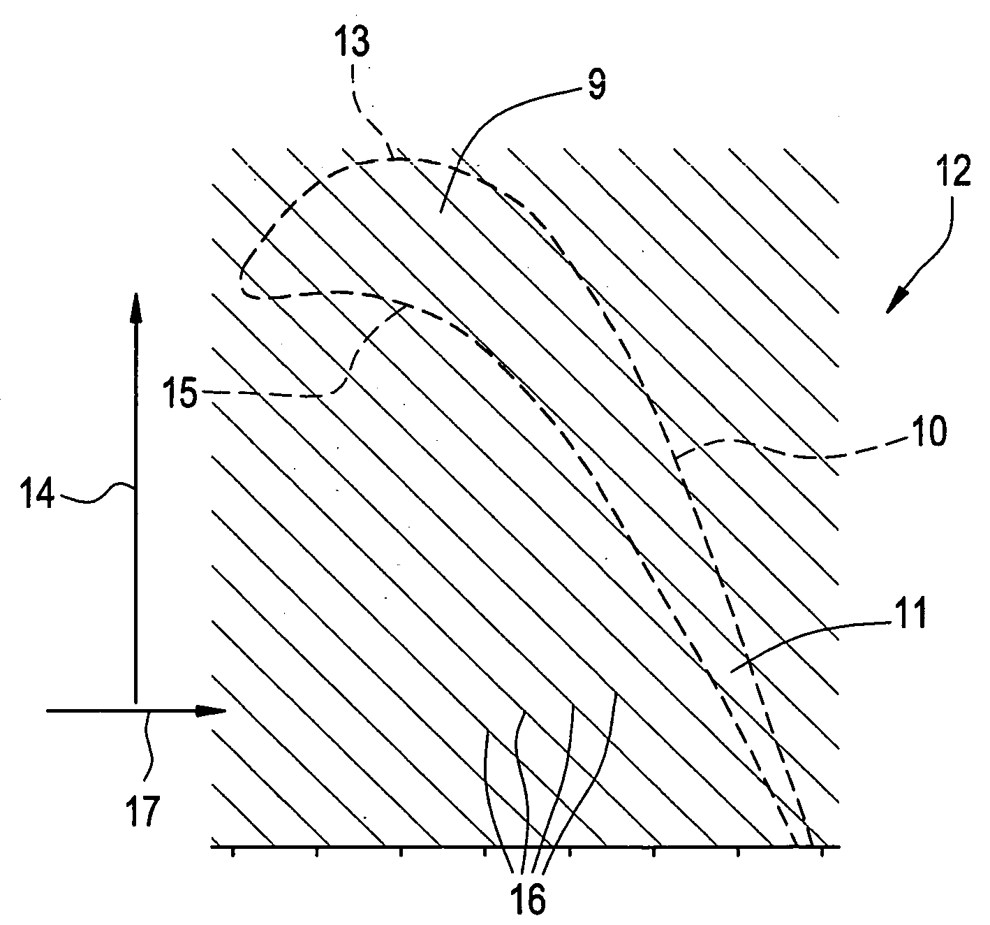
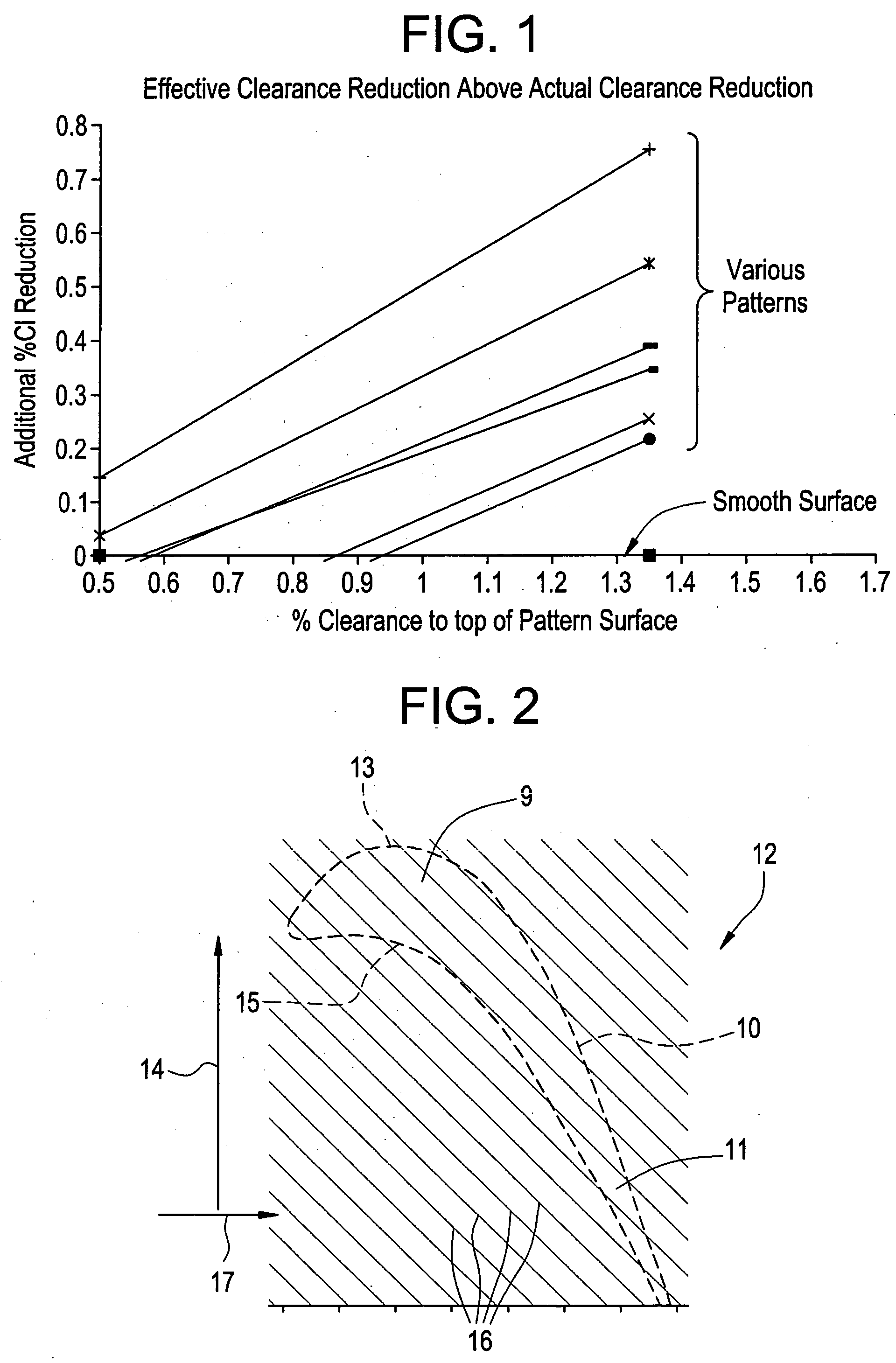
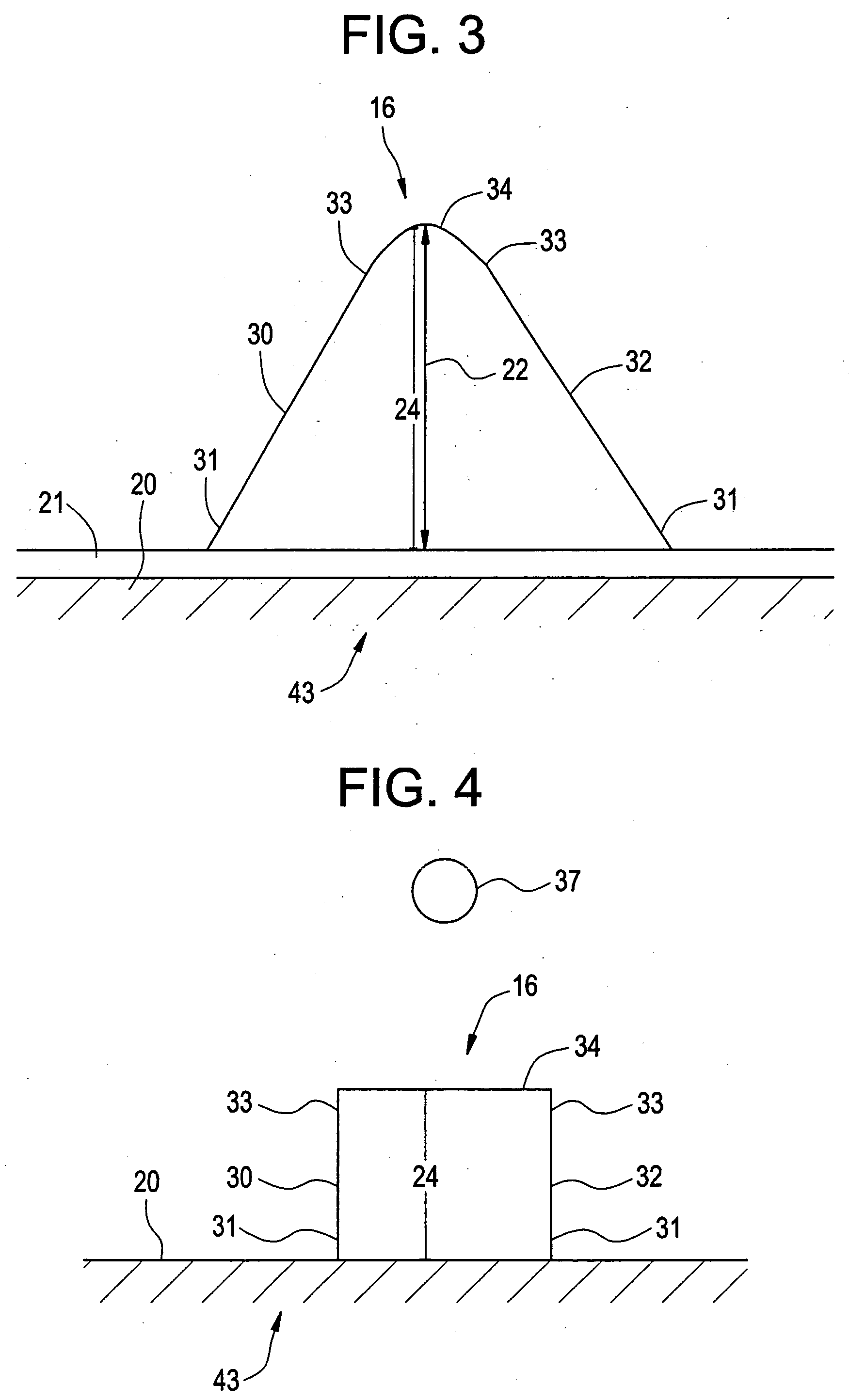
[0026] Exemplary embodiments of the present invention include an abradable coating defining a pattern that improves abradability of an abradable material and improves the aerodynamic performance of a turbine by improving a seal around a turbine bucket tip. Another exemplary embodiment includes the pattern formed in an interior surface of a turbine shroud. Generally, the pattern is formed from a plurality of ridges. Exemplary embodiments of the pattern improve aerodynamic performance of the turbine by decreasing a space between the turbine bucket tip and a turbine shroud, thereby improving the seal around the turbine bucket tip. An additional aerodynamic performance improvement is realized due to the pattern reducing aerodynamic losses between each turbine bucket tip of a plurality of turbine bucket tips. A patterned surface on the interior surface of the turbine shroud provides a direction to the mainstream flow on the outer wall. Thus, even if the seal were not improved, the patter...


PUM


Abstract

A pattern for improving aerodynamic performance of a turbine includes a material disposed in a pattern at a base surface of a turbine shroud such that the material is capable of abradable contact with a tip portion of a turbine bucket. The pattern includes a first plurality of ridges disposed at the base surface such that a first portion of the first plurality of ridges corresponding to a back portion of the turbine bucket is oriented at a first angle with respect to an axis of rotation of the turbine bucket. Each ridge of the first plurality of ridges has a first sidewall and a second sidewall having a first end and a second end. The first ends of the first and second sidewalls extend from the base surface. The first and second sidewalls slope toward each other with substantially equal but opposite slopes until meeting at the second ends of respective first and second sidewalls defining a centerline and a top portion of the ridge.

Description

BACKGROUND OF THE INVENTION [0001] The present invention relates to patterns placed at the surface of metal components of gas turbine engines, radial inflow compressors and radial turbines, including micro-turbines and turbo-chargers, that are exposed to high temperature environments and, in particular, to a new type of optimized pattern applied to turbine shrouds used in gas turbine engines in order to improve the performance and efficiency of the turbine blades (also known as “buckets”). [0002] Gas turbine engines are used in a wide variety of different applications, most notably electrical power generation. Such engines typically include a turbocompressor that compresses air to a high pressure by means of a multi-stage axial flow compressor. The compressed air passes through a combustor, which accepts air and fuel from a fuel supply and provides continuous combustion, thus raising the temperature and pressure of the working gases to a high level. The combustor delivers the high t...

Claims


Application Information

Patent Timeline
Patent Type & Authority Applications(United States)
IPC IPC(8): F01D5/20
CPCF01D11/12F01D11/122
Inventor NELSON, WARREN ARTHURARNESS, BRIAN PETERMARKS, PAUL THOMASCHUPP, RAYMOND EDWARDMCGOVERN, TARA EASTER
Owner GENERAL ELECTRIC CO
Why Eureka
Try Eureka