Large part polishing apparatus and polishing method

a technology for polishing apparatuses and large parts, applied in mechanical apparatuses, machines/engines, manufacturing tools, etc., can solve the problems of inability to apply apparatuses for polishing the surface of large parts such as turbine parts, complicated parts, and narrow parts, so as to enhance the quality of non-destructive inspection and polishing work, without lowering the surface roughness

Inactive Publication Date: 2006-05-25
KK TOSHIBA
View PDF8 Cites 22 Cited by
  • Summary
  • Abstract
  • Description
  • Claims
  • Application Information

AI Technical Summary

Benefits of technology

[0025] The invention is capable of polishing the surface of a large parts, such as a turbine nozzle, moving vane, large rotary part such as a turbine rotor, including a narrow part or fitting part which is hard to polis

Problems solved by technology

However, the apparatus cannot be applied for polishing the surface of large parts such as turbine part

Method used


Image

  • Large part polishing apparatus and polishing method
  • Large part polishing apparatus and polishing method
  • Large part polishing apparatus and polishing method

Examples


first embodiment

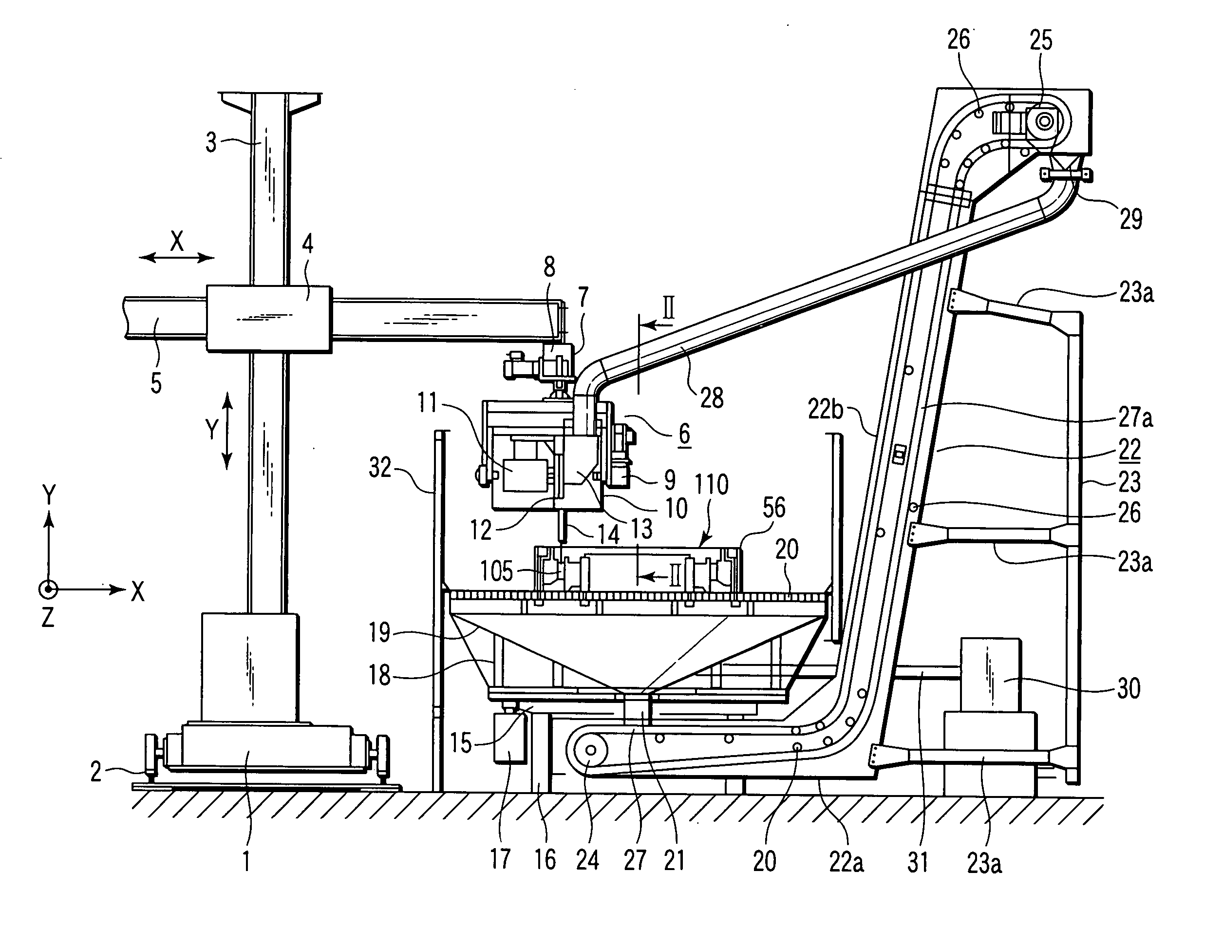
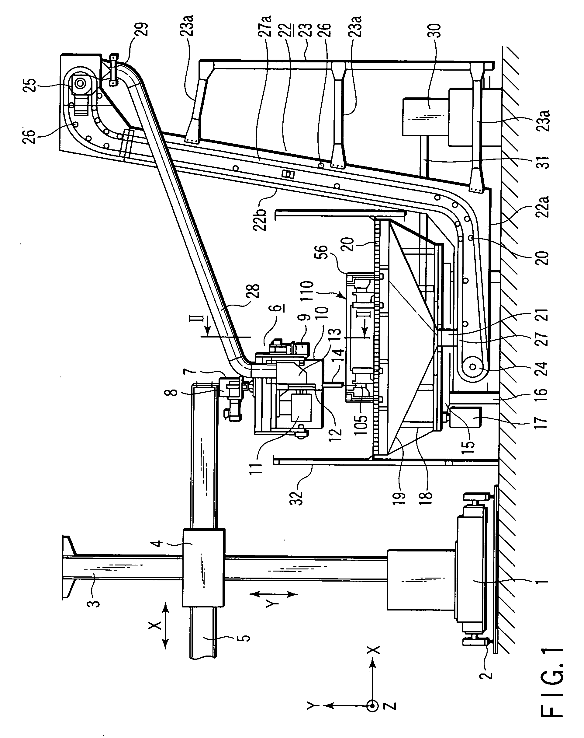
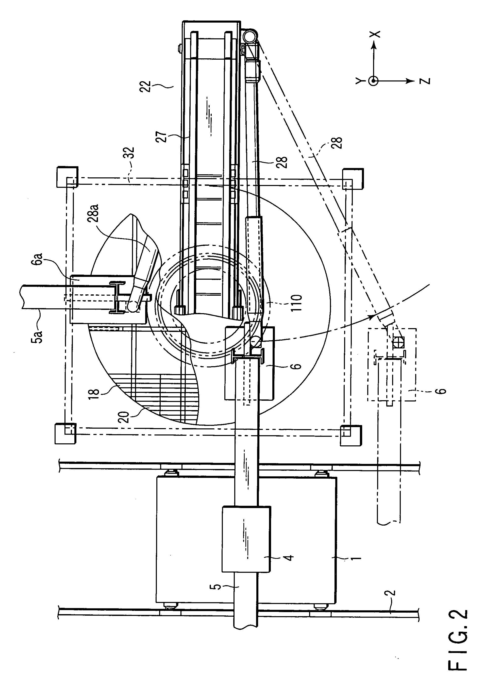
[0039]FIG. 1 is a front view showing a large part polishing apparatus according to the invention, and FIG. 2 is a plan view of the embodiment.

[0040] In FIGS. 1 and 2, reference numeral 1 is a carriage capable of moving in a direction of Z-axis (perpendicular direction in the drawing) along rails 2, and a stand 3 is mounted perpendicularly on the carriage 1. On the stand 3, a manipulator support portion 4 is mounted movably in a direction of Y-axis (vertical direction in the drawing), and a manipulator 5 is supported on the manipulator support portion 4 so as to be movable in a direction of X-axis (lateral direction in the drawing). The carriage 1, manipulator support portion 4, and manipulator 5 are driven in individual directions by driving sources which are not shown in the drawing.

[0041] Reference numeral 6 is a polishing head attached to the leading end of the manipulator 5 by way of a bracket 7, and this polishing head 6 is supported to be free to swirl in a horizontal directi...

second embodiment

[0070]FIG. 4 is a side view showing a large part polishing apparatus according to the invention, and FIG. 5 is a front view of the apparatus.

[0071] In FIGS. 4 and 5, reference numeral 41 is a carrier with lifter equipped with casters in the lower part, and a polishing apparatus main body 42 is mounted on the carriage 41 with lifter.

[0072] This polishing apparatus main body 42 comprises a recovery tank 45 for collecting abrasive particles 44 having an elastic material as a core, as an abrasive, in a case 43, a perpendicular conveying belt mechanism 46 for conveying the abrasive particles 44 in the recovery tank 45 to a proper height above the tank 45, an impeller 48 for giving rotary energy to the abrasive particles 44 supplied by way of a guide belt mechanism 47 after being conveyed above from the recovery tank 45 by way of this perpendicular conveying belt mechanism 46, and a trough-shaped injection nozzle 49 for injecting the abrasive particles 44 at high speed by determining the...

third embodiment

[0089]FIG. 8 is a side view showing a large part polishing apparatus according to the invention.

[0090] In FIG. 8, reference numeral 61 is a carriage with lifter having casters provided in the lower part, and a polishing apparatus main body 62 is mounted on the carriage 61 with lifter.

[0091] The polishing apparatus main body 62 comprises an internal tank 65 containing abrasive particles 64 made of elastic material as a core, as an abrasive, in a case 63 having an injection mechanism housing portion 63a extending in the horizontal direction in the upper part, a perpendicular conveying belt mechanism 66 for conveying the abrasive particles 64 in the internal tank 65 to a proper height above the tank 65, a horizontal conveying belt mechanism 67 for conveying the abrasive particles 64 conveyed upward from the internal tank 65 by the perpendicular conveying belt mechanism 66 to the injection mechanism housing portion 63a side, two impellers 68 disposed parallel along the horizontal conve...


PUM


Abstract

The present invention comprises a turntable which holds a turbine part at a predetermined position, the turn table being rotatably supported by a support member, and rotated and driven by a driving motor, an abrasive feeding unit which feeds an abrasive particle having an elastic material as a core to a predetermined position as an abrasive, and a polishing head including an impeller which is rotated and driven by an impeller driving motor at high speed and applies rotary energy to the abrasive particle to be supplied from the abrasive feeding unit, the polishing head injecting the abrasive particle flying from the tangential direction of the impeller at a predetermined speed toward a surface to be polished of the turbine part held on the turntable, and an abrasive recovery unit which recovers the abrasive particle provided for polishing of the turbine part from the polishing head, and feeding into the abrasive feeding unit.

Description

CROSS-REFERENCE TO RELATED APPLICATIONS [0001] This is a Continuation Application of PCT Application No. PCT / JP2004 / 006161, filed Apr. 28, 2004, which was published under PCT Article 21(2) in Japanese.BACKGROUND OF THE INVENTION [0002] 1. Field of the Invention [0003] The present invention relates to a large part polishing apparatus and polishing method for polishing a large structural part such as a steam turbine part by projecting and colliding an abrasive particle having an elastic material as a core to the surface thereof. [0004] 2. Description of the Related Art [0005] In steam turbines, in particular, moving vanes, stationary vanes, turbine rotors, and steam passage parts (for example, valve, steam tube, crossover tube, turbine inlet, turbine outlet, and nozzle box inside), their surface roughness has a key factor on the turbine performance, and it is required to improve the surface roughness (make smoother) of a steam passage as far as possible. [0006] The turbine parts are m...

Claims


Application Information

Patent Timeline
IPC IPC(8): B24C3/00B24C1/08B24C3/24B24C5/06B24C9/00B24C11/00F01D5/00F01D25/00
CPCB24C1/08B24C3/24B24C9/003B24C9/006B24C11/00F01D5/005F01D25/002F05D2230/14F05D2230/10F05D2230/90Y02P70/10
Inventor YANAKA, SATORUASAI, SATORUTSUBOI, RYUSUKEKAMIMURA, KENJITANUMA, TADASHIKIKUCHI, MASATAKA
Owner KK TOSHIBA
Why Eureka
Try Eureka