Methods and apparatus for processing fuels

a technology of combustible fuels and processing methods, applied in the direction of chemistry apparatus and processes, fuels, organic chemistry, etc., can solve the problems of increasing the amount of hydrogen peroxide or mixing time, affecting the quality of combustible fuels, and reducing the efficiency of combustible fuels

Inactive Publication Date: 2006-05-25
MECHAM LORRIE ELMER
View PDF2 Cites 17 Cited by
  • Summary
  • Abstract
  • Description
  • Claims
  • Application Information

AI Technical Summary

Benefits of technology

[0012] Process controls are also contemplated. For example, it is contemplated that systems and methods can be implemented that sense an undesirable amount of a triol and a glyceride or other byproduct in a downstream portion of the cleaned fuel. Especially preferred process controls are at least partially automated, and thereby automatically modify a parameter of the process to reduce the byproduct in an upstream portion of the cleaned fuel. For example, if excess triol is detected, the system can automatically or otherwise increase hydrogen peroxide or mixing time.

Problems solved by technology

Many fuels, especially reclaimed or renewable fuels such as biodiesel and fermentation derived ethanol, are heavily contaminated.
Upon combustion, the contaminants contribute to air pollution, and eventually water and soil pollution.
But such filters are notoriously slow, and therefore to a large extent impractical.
Unfortunately, that process is not commercially viable.
The process is too slow, is not amenable to continuous process, and is wasteful in that a considerable amount of fuel remains with the clay and water sludge at the bottom of the processing vessel.
Still further, there is no teaching or suggestion that the process can be applied to “raw” fuels, including for example, unfiltered biodiesel or fermentation derived ethanol, which can be heavily contaminated.

Method used


Image

  • Methods and apparatus for processing fuels

Examples


Embodiment Construction

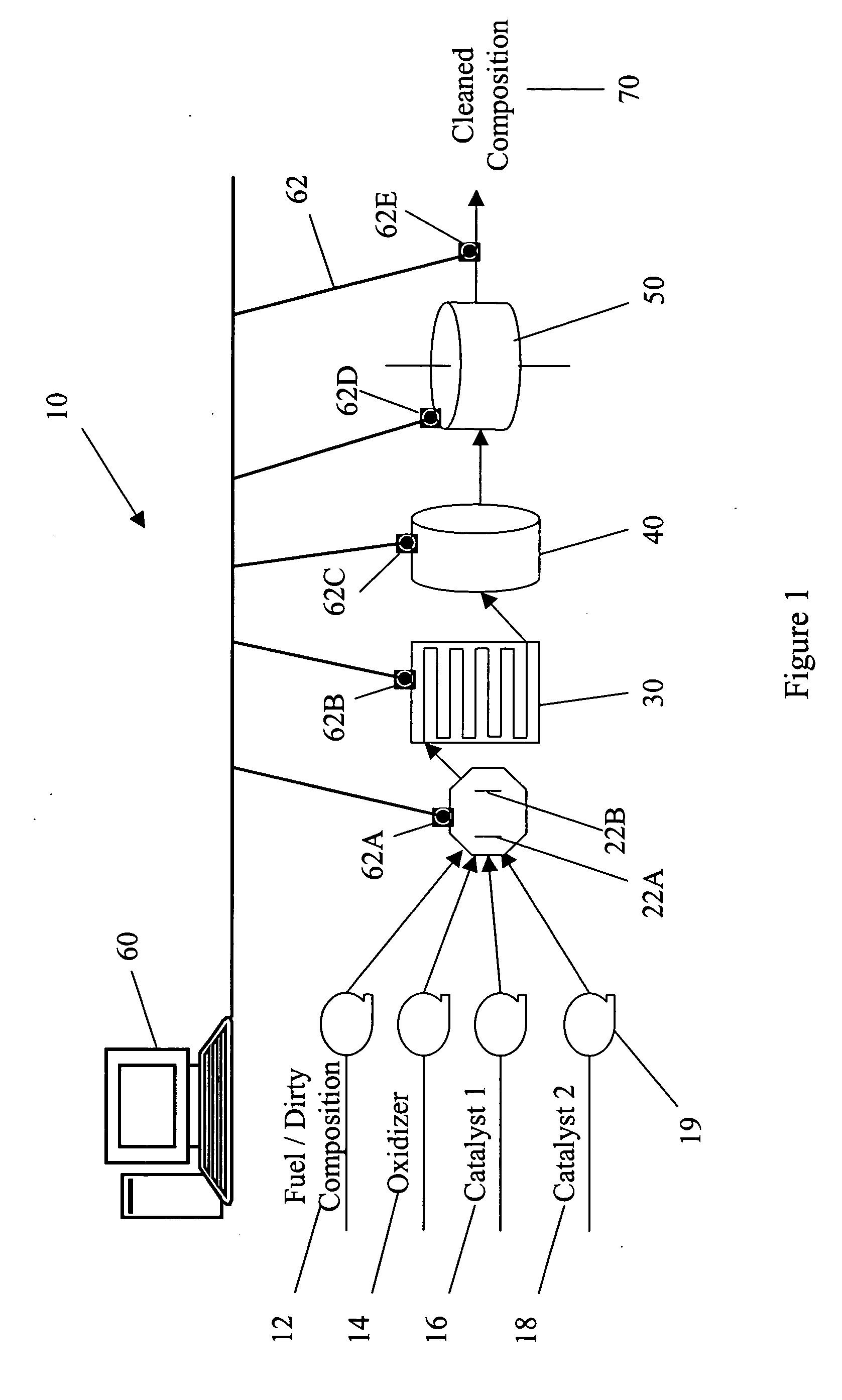
[0018] In FIG. 1, a purifying system 10 generally includes feed lines for input composition 12, oxidizer 14, first catalyst 16, second catalyst 18, a mixer 20, a separator 30, a filter 40, a centrifuge 50, computer controller 60, and an exit line 70. Pumps 19 provide motive force for movement of the corresponding compositions. In general, the vessels and various other conduction lines described herein are preferably made of stainless steel, glass, or other material that is non-reactive to the various chemicals.

[0019] Input composition 12 would usually be a liquid fuel, i.e. liquid that can reasonably be combusted to produce motive and / or heat energy. For example, fuel 12 is contemplated to include all manner of petroleum based compositions (e.g., gasoline, diesel, heating oil, and jet fuel), agriculturally based compositions (e.g., biodiesel, ethanol, olive, soybean, cotton, rapeseed, safflower, corn and other and vegetable oils), and non-petroleum, non-agriculturally based composi...


PUM

PropertyMeasurementUnit
capacity volumeaaaaaaaaaa
capacity volumesaaaaaaaaaa

Abstract

A fuel or other process fluid is cleansed by a) combining the fluid with water and an oxidizer; b) mixing the combination in a mixer having a volume V; c) separating the mixed combination into hydrophobic and hydrophilic phases; d) filtering the hydrophobic phase through a filter; e) removing water from the filtered hydrophobic phase to produce the cleaned fluid; and accomplishing steps a-d in a continuous manner that produces an output of the cleaned fuel at an average rate of at least 10V/hour. A centrifuge can optionally reduce water content of the cleaned fluid to no more than 5 ppm, more preferably no more than 1 ppm, and most preferably no more than 0.5 ppm.

Description

FIELD OF THE INVENTION [0001] The field of the invention is processing of combustible fuels. BACKGROUND [0002] Many fuels, especially reclaimed or renewable fuels such as biodiesel and fermentation derived ethanol, are heavily contaminated. Upon combustion, the contaminants contribute to air pollution, and eventually water and soil pollution. In some instances the contribution is strictly chemical, and in other instances the contribution can be some combination of chemical and physical interactions. For example, the current inventor has theorized that contaminant particles create hot spots that accelerate production of unburned and / or partially burned hydrocarbons, NOx, and particulates. [0003] It is known to remove particulates from dirty fuels using a paper, resin, or other physical filter. Filters with micron sized holes, for example, can and have been used to reduce contaminants in fuels. But such filters are notoriously slow, and therefore to a large extent impractical. [0004] ...

Claims


Application Information

Patent Timeline
Patent Type & Authority Applications(United States)
IPC IPC(8): C07C7/00
CPCC10G27/00C10G27/04C10G33/06C10G53/14C10L1/00
Inventor MECHAM, LORRIE ELMER
Owner MECHAM LORRIE ELMER
Why Eureka
Try Eureka