Heat treatment method and device for piping

a heat treatment method and piping technology, applied in heat treatment apparatus, furnaces, manufacturing tools, etc., can solve the problems increase the risk of stress corrosion cracking, and achieve the effect of preventing stress corrosion cracking in the piping system

Inactive Publication Date: 2006-06-01
HITACHI LTD
View PDF1 Cites 22 Cited by
  • Summary
  • Abstract
  • Description
  • Claims
  • Application Information

AI Technical Summary

Benefits of technology

[0011] According to the present invention, after a piping system of a plant is assembled, a compressive residual stress can be generated in the inside surface of

Problems solved by technology

Therefore, if the pipe is used in a severely corrosive environment in a state wherein the material has been sensitized, stress corrosion cracking occurs.
That is, when three factors of sensitization of the material, a high tensile residual stress, and a corrosive environment,

Method used


Image

  • Heat treatment method and device for piping
  • Heat treatment method and device for piping
  • Heat treatment method and device for piping

Examples


Embodiment Construction

[0025] A first embodiment of the present invention will be described with reference to FIGS. 1 to 7.

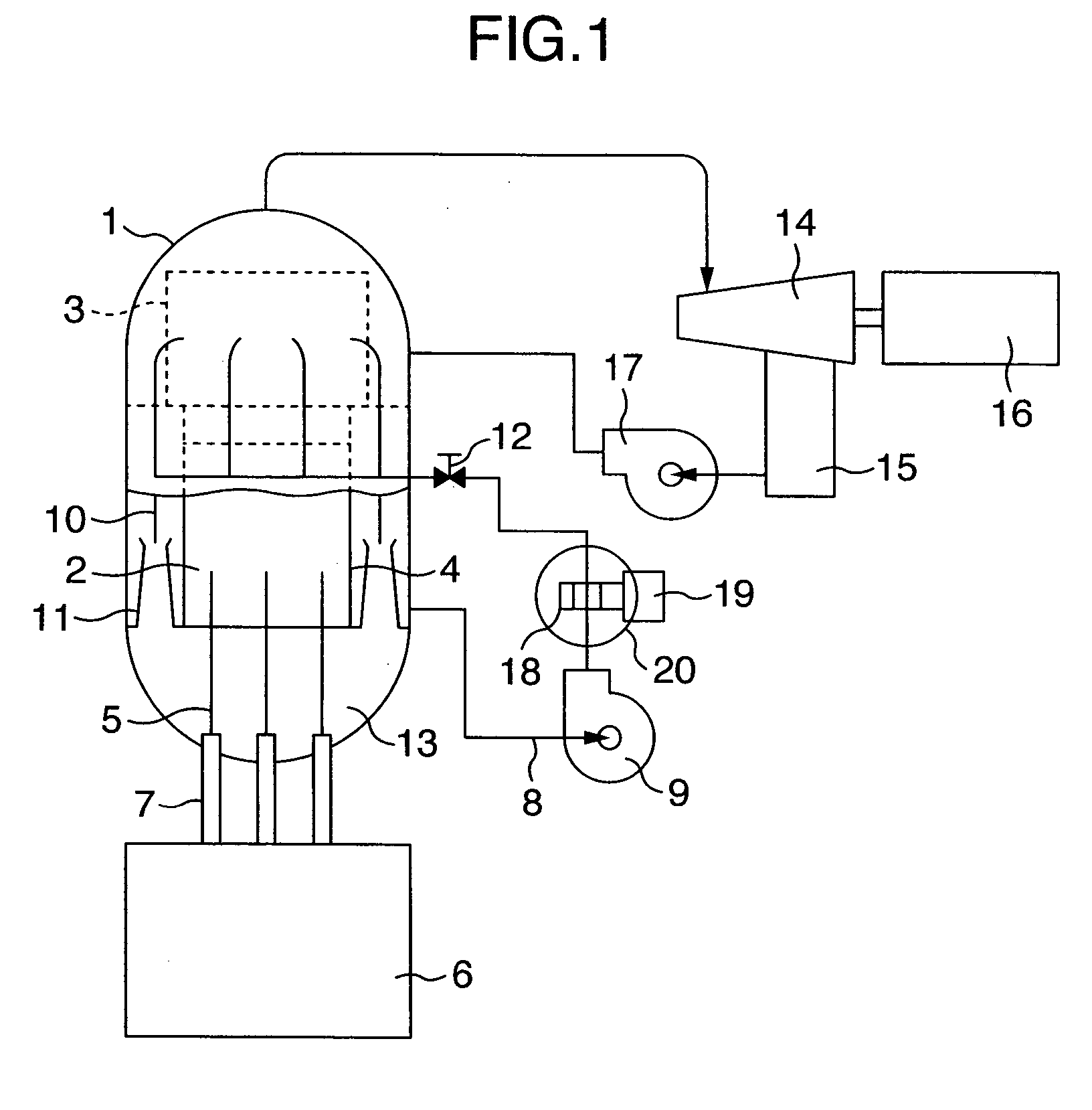
[0026]FIG. 1 shows the first embodiment in which the present invention is applied to a nuclear power plant with a boiling-water reactor.

[0027] A reactor pressure vessel 1 has therein an in core portion 2 to be charged with nuclear fuel; a steam water separator 3; and a core shroud 4 surrounding the in core portion 2. A plurality of control rods 5 are inserted in the in core portion 2. The control rods 5 are operated by a control rod driving system 7 under the control of a control rod drive controller 6.

[0028] The interior of the reactor pressure vessel 1 is filled up with light water as cooling water to a somewhat upper portion of the in core portion 2. When the reactor is in operation, by driving a circulating pump 9 provided for a pipe 8, the cooling water in the reactor pressure vessel 1 passes through the pipe 8 and a riser tube 10 (connected to the pipe 8) of a primary loop re...


PUM

PropertyMeasurementUnit
Temperatureaaaaaaaaaa
Distanceaaaaaaaaaa

Abstract

In a method for heat treatment of an existing pipe constituting a piping system, for converting the residual stress at a welded metallic portion and a welding heat influenced portion of the inside surface of the pipe, into a compressive stress and thereby generate the compressive stress in the inside surface of the existing pipe, a coolant is retained in the pipe; an arbitrary portion of the outside surface of the pipe is heated; thereby a temperature distribution little in temperature difference is produced in the wall surface of the pipe at the heated portion; and then the coolant is allowed to flow. By converting the residual stress at the welded metallic portion and the welding heat influenced portion of the inside surface of the pipe, into the compressive stress, stress corrosion cracking generated from the welded metallic portion and the welding heat influenced portion can be suppressed.

Description

BACKGROUND OF THE INVENTION [0001] 1. Field of the Invention [0002] The present invention relates to a method for converting a tensile residual stress existing in an inside surface of a pipe constituting a piping system of a plant, into a compressive residual stress to suppress stress corrosion cracking. [0003] 2. Description of the Related Art [0004] In a welded portion of stainless steel or nickel-base alloy steel, chromium carbide is separated out at a crystal grain boundary due to heat of welding. As a result, a chromium-lack layer is produced near the pole of the grain boundary, and sensitization (a phenomenon that the sensitivity to corrosion increases) occurs in the chromium-lack layer. On the other hand, a high tensile residual stress is generally generated in the surface near a welded portion of a pipe constituting a piping system of a plant. Therefore, if the pipe is used in a severely corrosive environment in a state wherein the material has been sensitized, stress corros...

Claims


Application Information

Patent Timeline
IPC IPC(8): C21D9/08
CPCC21D1/42C21D9/08C21D9/50Y02P10/25
Inventor SAITOU, NOBORUYANAGIDA, NOBUYOSHIHAYASHI, SHOJIKANNO, SATOSHIENOMOTO, KUNIO
Owner HITACHI LTD
Why Eureka
Try Eureka