
Laser cutting method

a laser beam and cutting method technology, applied in the field of cutting methods, can solve the problems of reducing the cutting operation start point, affecting the cutting operation, so as to reduce the deviation of the crack

Active Publication Date: 2006-06-01
CANON KK
View PDF29 Cites 13 Cited by
  • Summary
  • Abstract
  • Description
  • Claims
  • Application Information

AI Technical Summary

Benefits of technology

[0012] At least one exemplary embodiment is directed to a laser cutting method for forming a crack connecting a surface of a workpiece (i.e., a member to be cut)

Problems solved by technology

However, according to this method, not only the portion directly irradiated with the laser beam but also its peripheral region on the substrate surface will melt.
The electronic devices provided on the semiconductor substrate will be damaged.
However, according to the above-described conventional method, the start point of a cutting operation is limited to an internal region of the substrate where the laser beam is condensed.
Hence, it can be difficult to appropriately control the direction or position of a crack growing from the start point of the cutting operation to the substrate surface.
Especially, in a workpiece made of a silicon wafer or a material having a similar crystal structure, the crack tends to grow along the crystal orientation.
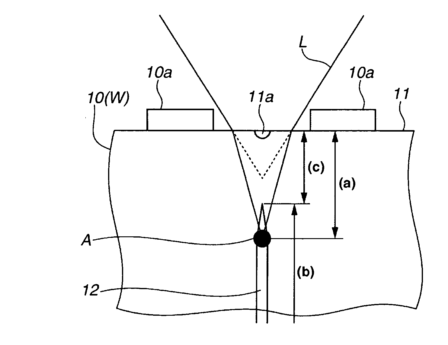
Therefore, according to the above-described laser processing method, if there is a small offset between a predetermined cutting line and a crystal orientation reaching the substrate surface that may be present due to manufacturing errors in the formation of the silicon substrate or elements, the crack may deviate from the predetermined cutting line in the process of growing toward the substrate surface and, as a result, may damage the logic circuits provided on a semiconductor element region.

Method used


Image

  • Laser cutting method
  • Laser cutting method
  • Laser cutting method

Examples


Embodiment Construction

[0030] The following description of exemplary embodiment(s) is / are merely illustrative in nature and is in no way intended to limit the invention, its application, or uses.

[0031] Processes, techniques, apparatus, and materials as known by one of ordinary skill in the art may not be discussed in detail but are intended to be part of the enabling description where appropriate. For example certain lasers and optical lens systems may not be discussed in detail. However these systems and the methods to fabricate these system as known by one of ordinary skill in the relevant art is intended to be part of the enabling disclosure herein where appropriate.

[0032] Note that similar reference numerals and letters refer to similar items in the following figures, and thus once an item is defined in one figure, it may not be discussed for following figures.

[0033] Note that the non-limiting illustrative examples that follow discuss the use of a silicon substrate, however exemplary embodiments ar...


PUM

PropertyMeasurementUnit
Forceaaaaaaaaaa
Depthaaaaaaaaaa
Distanceaaaaaaaaaa

Abstract

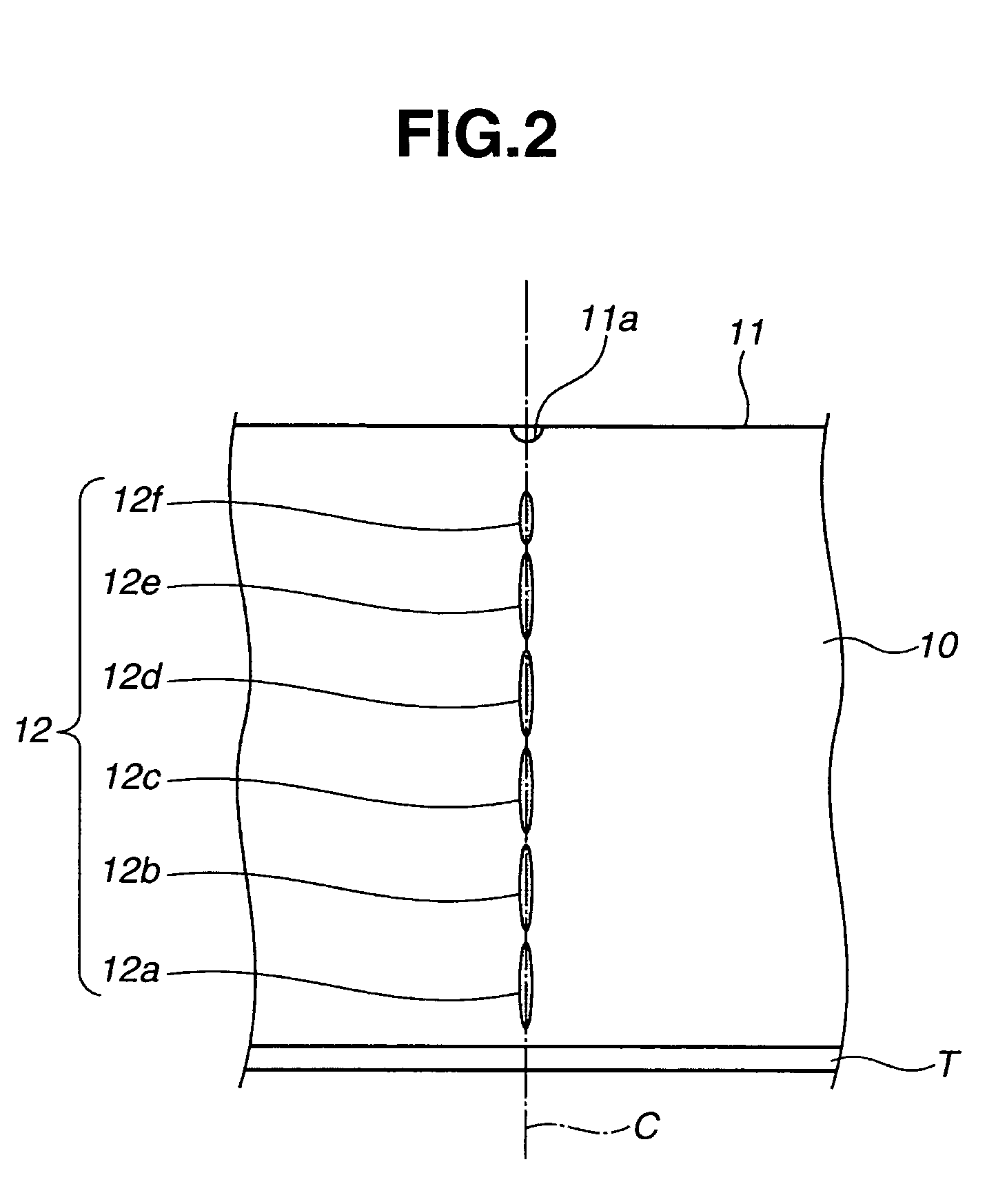
At least one exemplary embodiment is directed to a laser cutting method where a laser beam is condensed at internal points inside a substrate forming processing regions, and where the laser is swept along a cutting line, where the cutting line is associated with a recess on the substrate and where the recess can be formed contemporaneously with the formation of the processing regions.

Description

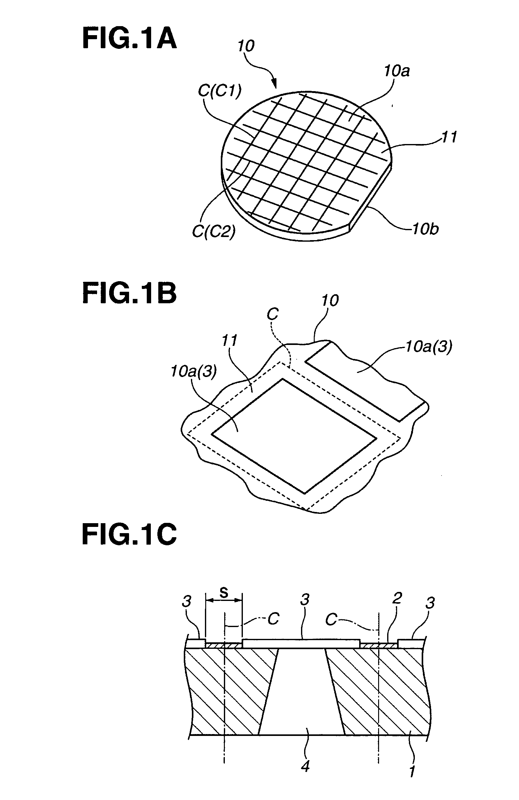
BACKGROUND OF THE INVENTION [0001] 1. Field of the Invention [0002] The present invention relates to a cutting method for cutting a workpiece with a laser beam, more particularly, though not exclusively, a laser beam condensed at an internal point of the workpiece. [0003] 2. Description of the Related Art [0004] According to a conventional technique for cutting a workpiece (i.e., a member to be cut) with a laser beam, the workpiece such as a semiconductor substrate is cut by rotating, at a high speed, a circular blade having a width of several tens μm to several hundreds μm so that the abrasive material on the blade surface can grind the workpiece (semiconductor substrate). This method is generally referred to as a blade dicing method. [0005] According to this method, to reduce heat generation or abrasion during the cutting operation, one can spray cooling water onto the cut surface. However, according to this method, finely powdered workpiece material or fine particles of the abras...

Claims


Application Information

Patent Timeline
IPC IPC(8): B23K26/38C03B33/09B23K26/364
CPCB23K26/0057B23K26/0853B23K26/367Y10T29/49401B23K26/4075B23K2201/40B23K26/38B23K26/40B23K26/364B23K26/53B23K2101/40B23K2103/50
Inventor INADA, GENJIIRI, JUNICHIRONISHIWAKI, MASAYUKISUGAMA, SADAYUKI
Owner CANON KK
Learn More