X-ray computed tomography scanner and x-ray detecting system

a computed tomography and scanner technology, applied in the direction of instruments, x/gamma/cosmic radiation measurement, radiofrequency measurement devices, etc., can solve the problems of difficult to take many slices of images over a large range of a body being examined in a short time, conventional detection systems described above have various unsolved problems, etc., to achieve excellent uniformity, suppress radiation noise, and high stability

Active Publication Date: 2006-06-01
TOSHIBA MEDICAL SYST CORP
View PDF7 Cites 5 Cited by
  • Summary
  • Abstract
  • Description
  • Claims
  • Application Information

AI Technical Summary

Benefits of technology

[0028] In the X-ray computed tomography scanner and the X-ray detecting system according to the present invention, the X-ray detecting system is formed so as to suppress radiation noise caused by fluctuations of ground voltages of the plurality of detector blocks and so as to handle variations in operating characteristics among detector blocks due to variations of power supply voltage among detector blocks. Thus, high stability and excellent uniformity are achieved in the X-ray detecting operation, thereby making it possible to improve image quality. Besides, a reduction of physical size of the system is also achieved.

Problems solved by technology

In early types of X-ray CT scanners, it is capable of taking only a single slice of image at a time, and thus it is difficult to take many slices of images over a large range of a body being examined in a short time.
In the typical X-ray CT scanner, the DAS usually has high circuit complexity to deal with as many channels as 500 to a few ten thousand channels.
The conventional detection system described above has various unsolved problems.
A first unsolved problem relates to grouping of the DAS.
Because the ground line of the electric circuit of the DAS is substantially isolated from the base frame, when the whole circuit of the DAS is operated in synchronization with the single oscillator, the ground level of the DAS has a fluctuation that causes noise to radiate from the ground line of the DAS and thus causes degradation in image quality.
Furthermore, the isolated ground causes a secondary problem that the fluctuation of the ground level of the DAS influences an operation of an analog signal.
Another problem is that a voltage drop occurs along the power cable via which the electric power is supplied to the detection system.
This produces non-uniformity of the operating characteristics of the DAS part among detector blocks.
However, the both techniques cause an unacceptably large increase in space where the detection system is disposed, and thus both techniques cannot be realistic solutions.

Method used


Image

  • X-ray computed tomography scanner and x-ray detecting system
  • X-ray computed tomography scanner and x-ray detecting system
  • X-ray computed tomography scanner and x-ray detecting system

Examples


first embodiment

[0048] A first embodiment will now be described below with reference to FIGS. 1 to 9.

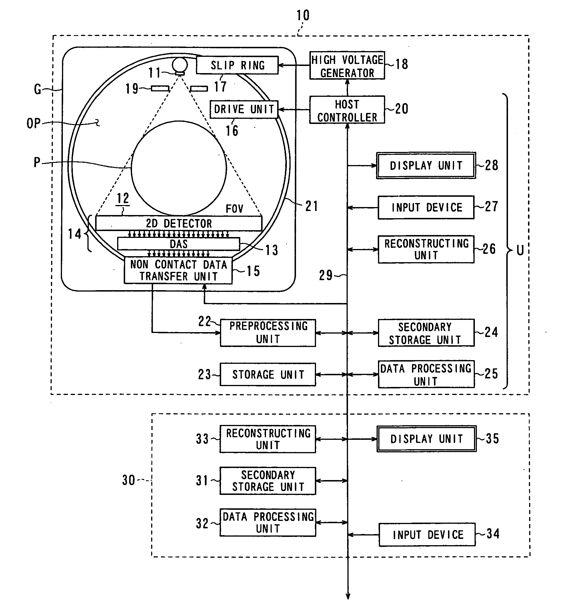
[0049]FIG. 1 shows a multi-slice X-ray CT scanner according to the first embodiment of the present invention. This multi-slice CT scanner is capable of performing not only multi-slice helical scanning but also conventional scanning (single-slice scanning and multi-slice scanning). As shown in FIG. 1, the multi-slice CT scanner 10 includes a bed (not shown) on which to lay a body (patient) P to be examined, a base frame G having a diagnosis cavity OP through which to insert the body P, for acquiring projection image data associated with the body P, and a data processing unit U for controlling the operation of the whole base frame G, reconstructing the projection data into an image, and displaying the resultant image.

[0050] The bed includes a top plate slidable in a longitudinal direction by a bed driving unit (not shown). In most cases, the body P is laid such that the axis of the body is parallel ...

second embodiment

[0082] Referring to FIGS. 13 to 15, a second embodiment of the present invention will now be described below.

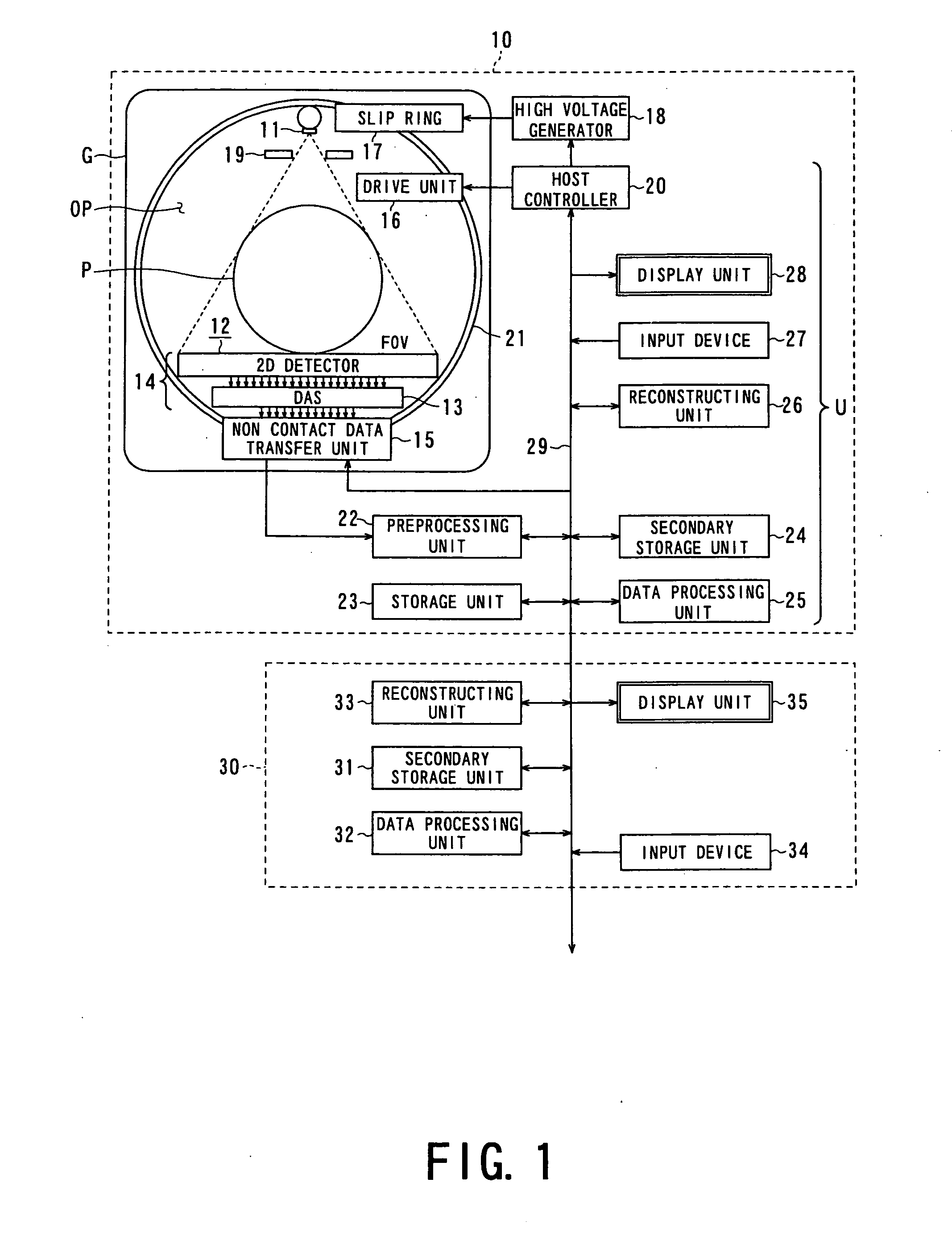
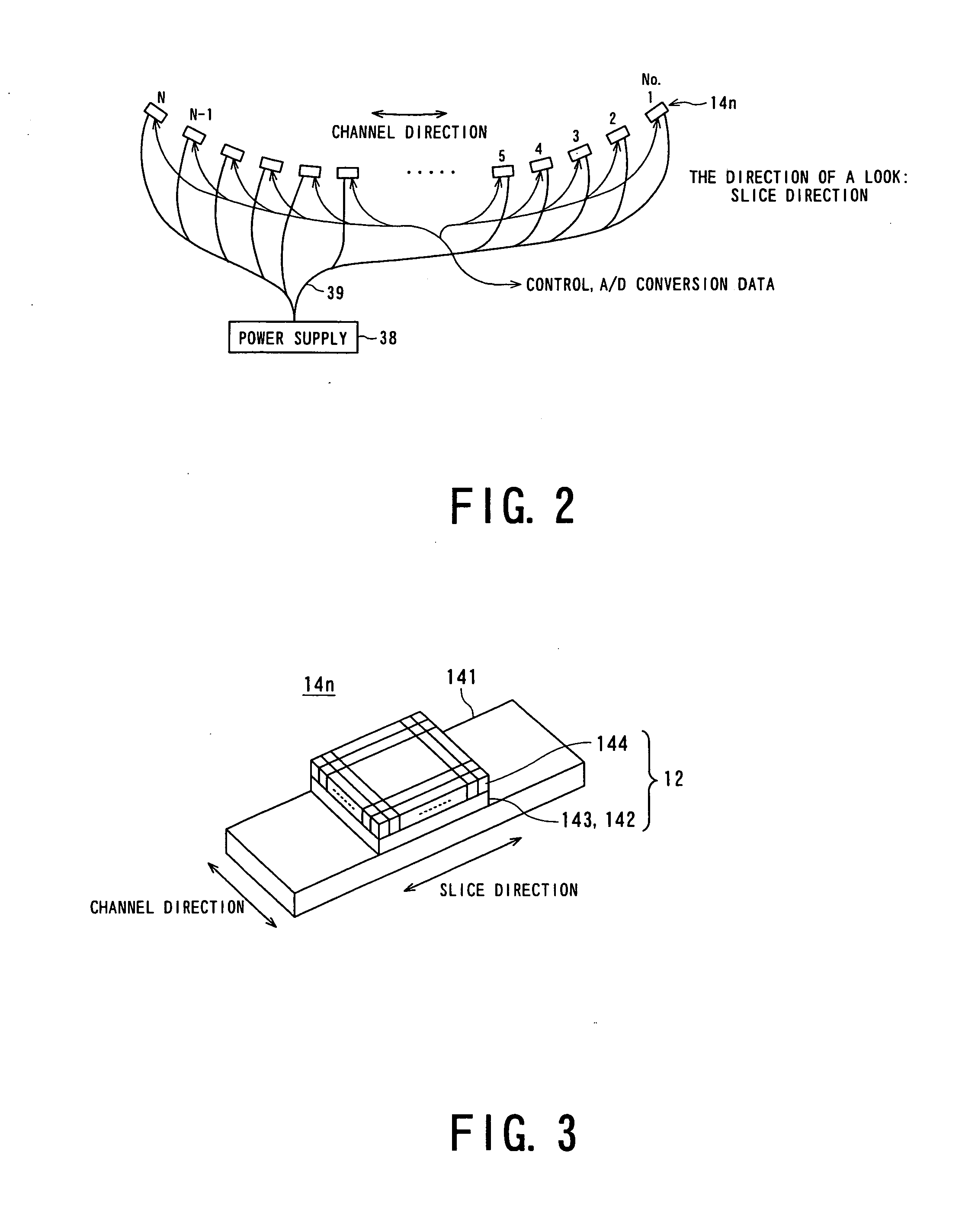
[0083] This second embodiment relates to a technique to adjust the voltage of respective detector blocks 14n of the X-ray detection system 14 in the X-ray CT scanner. The X-ray CT scanner according to the second embodiment is generally similar to that according to the first embodiment described above. Similar parts to those in the first embodiment are denoted by similar reference numerals, and a duplicated description thereof is not given herein.

[0084] In this second embodiment, as shown in FIG. 13, each detector block 14n has a power connector 61 and a voltage regulator 62 disposed on a surface, facing the DAS, of a printed circuit board 141. As shown in FIG. 14, an output terminal of a power supply 63 and the power connector 61 of each detector block 14n is connected to an output terminal of a power supply 63 via a cable 64, and thus electric power is supplied to the volt...

third embodiment

[0089] Referring to FIGS. 16 and 17, a third embodiment of the present invention will now be described below.

[0090] This third embodiment relates to the structure of the power supply line of each detector block 14n of the X-ray detection system 14 in the X-ray CT scanner. Except for the structure of the power supply line, the X-ray CT scanner according to the second embodiment is basically similar to that according to the first embodiment described above.

[0091] In the X-ray detection system 14 according to the present embodiment, as shown in FIG. 16, a power supply line supplying a (positive) power supply voltage to respective detector blocks 14n is formed of a plate-shaped metal bar 71. More specifically, a power supply voltage is supplied from a power supply 72 to the X-ray detection system 14 via a cable 73, and further supplied to the respective detector blocks 14n inside the X-ray detection system 14 via the metal bar 71. As shown in FIG. 17, the metal bar 71 has branches 71a...


PUM


Abstract

There is provided an X-ray detection system comprising a detector and a data acquisition unit. The detector detects an X-ray passing through a body being examined and producing an analog electric signal corresponding to the X-ray for each channel. The data acquisition unit includes a plurality of circuit blocks each including as many circuits as the number of channels assigned to each block. The data acquisition unit converts the analog electric signal output from the detector into a digital signal for each channel and outputting the resultant digital signal and a phase control unit controlling the phase of the circuit blocks of the data acquisition unit such that the circuit blocks are grouped into a plurality of groups and the respective groups of circuit blocks operate in synchronization with clock signals whose phase are different at least between two groups.

Description

CROSS REFERENCES TO RELATED APPLICATIONS [0001] The present application relates to and incorporates by reference Japanese Patent application No. 2003-199378 filed on 18, 2003. BACKGROUND OF THE INVENTION [0002] 1. Field of the Invention [0003] The present invention relates to an X-ray computed tomography scanner and an X-ray-detection system, and more particularly, to an X-ray computed tomography scanner and an X-ray detection system, in which problems caused by noise or a fluctuation of an operating voltage in a detector or a DAS (data acquisition system) are solved thereby achieving a stable and reliable operation. [0004] 2. Description of the Related Art [0005] An X-ray computed tomography scanner (hereinafter, referred to as an X-ray CT scanner) is known as one of computed tomography apparatuses. The X-ray CT scanner has been widely used for a long time as a tool of medical diagnosis and various medical research works. Since its advent, the X-ray CT scanner has progressed greatl...

Claims


Application Information

Patent Timeline
Patent Type & Authority Applications(United States)
IPC IPC(8): G01T1/24
CPCG01T1/1641G01T1/166G01T1/164
Inventor SUGIHARA, NAOKINAKAYAMA, MICHITOSUZUKI, TATSURO
Owner TOSHIBA MEDICAL SYST CORP
Why Eureka
Try Eureka