Piezoelectric vibrator, method of manufacturing the same, oscillator, electronic apparatus, and wave clock

Inactive Publication Date: 2006-06-01
SII CRYSTAL TECH
View PDF3 Cites 7 Cited by
  • Summary
  • Abstract
  • Description
  • Claims
  • Application Information

AI Technical Summary

Benefits of technology

[0021] Accordingly, an object of the prevent invention is to provide a piezoelectric vibrator which suppresses variation of characteristics such as a resonance resistance value and an os

Problems solved by technology

A vibrator in which a piezoelectric vibrator piece is stuck to a ceramic base using an adhesive has a problem that the vibrator piece is peeled off to stop oscillation upon a drop impact test.
However, in the constant temperature and humidity test 2, two failures (failure occurrence rate: 6.7%) occurs in lot 1 and one failure (failure occurrence rate: 3.3%) occurs in lot 2.
As the result of microscopic observation of the sample failure, it is confirmed that the bonding film was corroded.
The failure is caused by the frequency varia

Method used


Image

  • Piezoelectric vibrator, method of manufacturing the same, oscillator, electronic apparatus, and wave clock
  • Piezoelectric vibrator, method of manufacturing the same, oscillator, electronic apparatus, and wave clock
  • Piezoelectric vibrator, method of manufacturing the same, oscillator, electronic apparatus, and wave clock

Examples


second embodiment

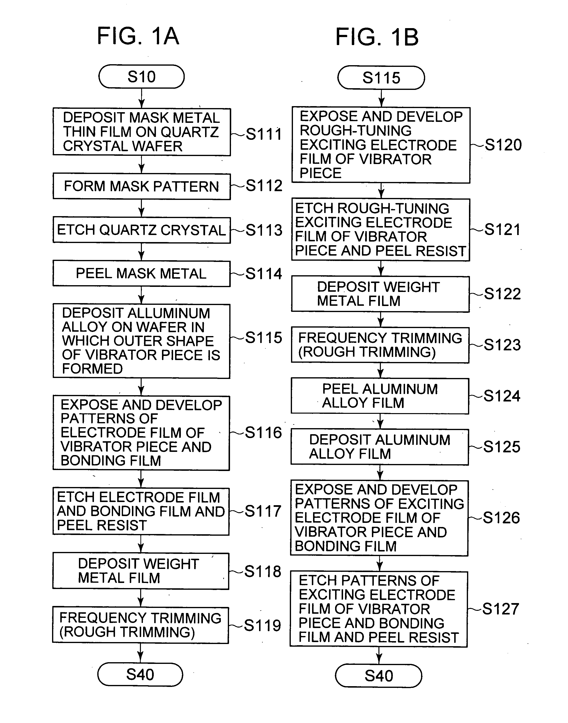
[0070] Next, a process of forming a vibrator piece and a frame in a method of manufacturing a piezoelectric vibrator according to the invention will be described. FIG. 1B is a flowchart for more improving bonding characteristics in consideration of cleanliness of the surface of the bonding film, and is obtained by changing the steps 116 to 119 in the flowchart of FIG. 1A. The process after the step 116 will now be schematically described.

[0071] By the step 115, the rough-trimming exciting electrode film on the quartz crystal wafer on which the aluminum alloy film is deposited is exposed and developed (step 120). Subsequently, the aluminum alloy film is etched and the resist film is peeled (step 121). At this time, only the pattern of the rough-trimming exciting electrode film is formed on the vibrator piece and the pattern of the bonding film is not formed. Next, a weight metal film is deposited (step 122). Thereafter, the rough frequency trimming is performed (step 123).

[0072] In ...

third embodiment

[0093]FIG. 6 is a schematic view illustrating a construction of a tuning fork type quartz oscillator according to the invention, and is a plan view of a surface mount type piezoelectric vibrator using the tuning fork type quartz crystal vibrator.

[0094] In FIG. 6, a tuning fork type quartz crystal vibrator 41 is disposed at a predetermined position of a substrate 42 and an integrated circuit 43 for an oscillator is disposed adjacent to the quartz crystal vibrator. In addition, an electronic part 44 such as a capacitor is mounted. These elements are electrically connected to one another through wiring patterns (not shown). The mechanical vibration of the vibrator piece of the tuning fork type quartz crystal vibrator 41 is converted into an electrical signal by piezoelectric characteristics of the quartz crystal and input to the integrated circuit 43. The integrated circuit 43 functions as an oscillator for processing a signal and outputs a frequency signal. These elements are molded w...

fourth embodiment

[0096]FIG. 7 is a schematic block diagram of an electronic apparatus according to the invention. The electronic apparatus is a wristwatch type communication apparatus having a watch function and a communication function, which has the substantially same appearance as that of a wristwatch and is more miniaturized and lightweight compared with a conventional portable telephone.

[0097] In FIG. 7, reference numeral 101 denotes a power supply unit for supplying power to each function unit described later, which is realized, for example, by a lithium ion secondary battery. The power supply unit 101 is connected to a control unit 102, a timing unit 103, a communication unit 104, a voltage detecting unit 105, and a display unit 107 in parallel and supplies power to each function unit.

[0098] The control unit 102 controls each function unit to control the entire operations of the system such as transmission / reception of voice data and measurement or display of current time. The control unit 1...


PUM

PropertyMeasurementUnit
Angleaaaaaaaaaa
Sizeaaaaaaaaaa
Sizeaaaaaaaaaa

Abstract

Provided is a method of manufacturing a piezoelectric vibrator including: forming integrally a vibrator piece and a frame surrounding the vibrator piece on a first wafer and forming bonding films on the both surfaces of the frame; forming a through-hole at a position corresponding to the frame of the first wafer in any one of a second wafer and a third wafer; sticking the second wafer and the third wafer on the both surfaces of the first wafer, respectively; and cutting the stuck wafers at a predetermined position. Here, the forming of the vibrator piece and the frame includes forming a non-bonding film area smaller than the through-hole at a position corresponding to the through-hole of the bonding film, and the cutting of the wafers includes cutting the wafers such that the non-bonding film area is divided.

Description

BACKGROUND OF THE INVENTION [0001] 1. Field of the Invention [0002] The present invention relates to a piezoelectric vibrator, a method of manufacturing the same, and an oscillator, an electronic apparatus and a wave clock including the piezoelectric vibrator. [0003] 2. Description of the Related Art [0004] Recently, a piezoelectric vibrator having a small size and high reliability is required for electronic apparatuses such as portable telephones, portable personal digital assistants, AV apparatuses, OA apparatuses, and in-vehicle apparatuses. A vibrator in which a piezoelectric vibrator piece is stuck to a ceramic base using an adhesive has a problem that the vibrator piece is peeled off to stop oscillation upon a drop impact test. As an example of means for solving this problem, there are provided a surface mount type piezoelectric vibrator which has a frame integrally connected to one end of a vibrator piece and including bonding films at the both surfaces thereof, and is compos...

Claims


Application Information

Patent Timeline
IPC IPC(8): H04R17/00
CPCY10T29/42H04R17/00
Inventor NAKAMURA, KISHIRO
Owner SII CRYSTAL TECH
Why Eureka
Try Eureka