
Regulated current mirror

a current mirror and circuit technology, applied in the direction of dc-amplifiers with dc-coupled stages, electric variable regulation, amplifiers, etc., can solve the problems of poor dynamics, limited operating characteristics, and lack of headroom, so as to improve the precision of the current mirror, improve the regulation, and improve the effect of regulation

Inactive Publication Date: 2006-06-01
AMI SEMICON BELGIUM
View PDF6 Cites 10 Cited by
  • Summary
  • Abstract
  • Description
  • Claims
  • Application Information

AI Technical Summary

Benefits of technology

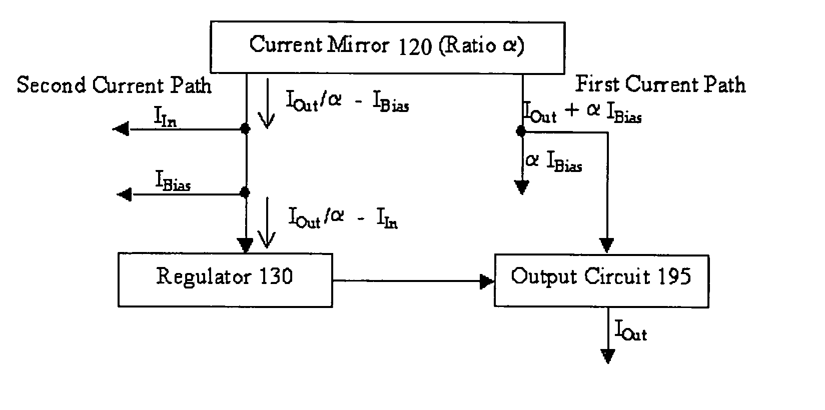
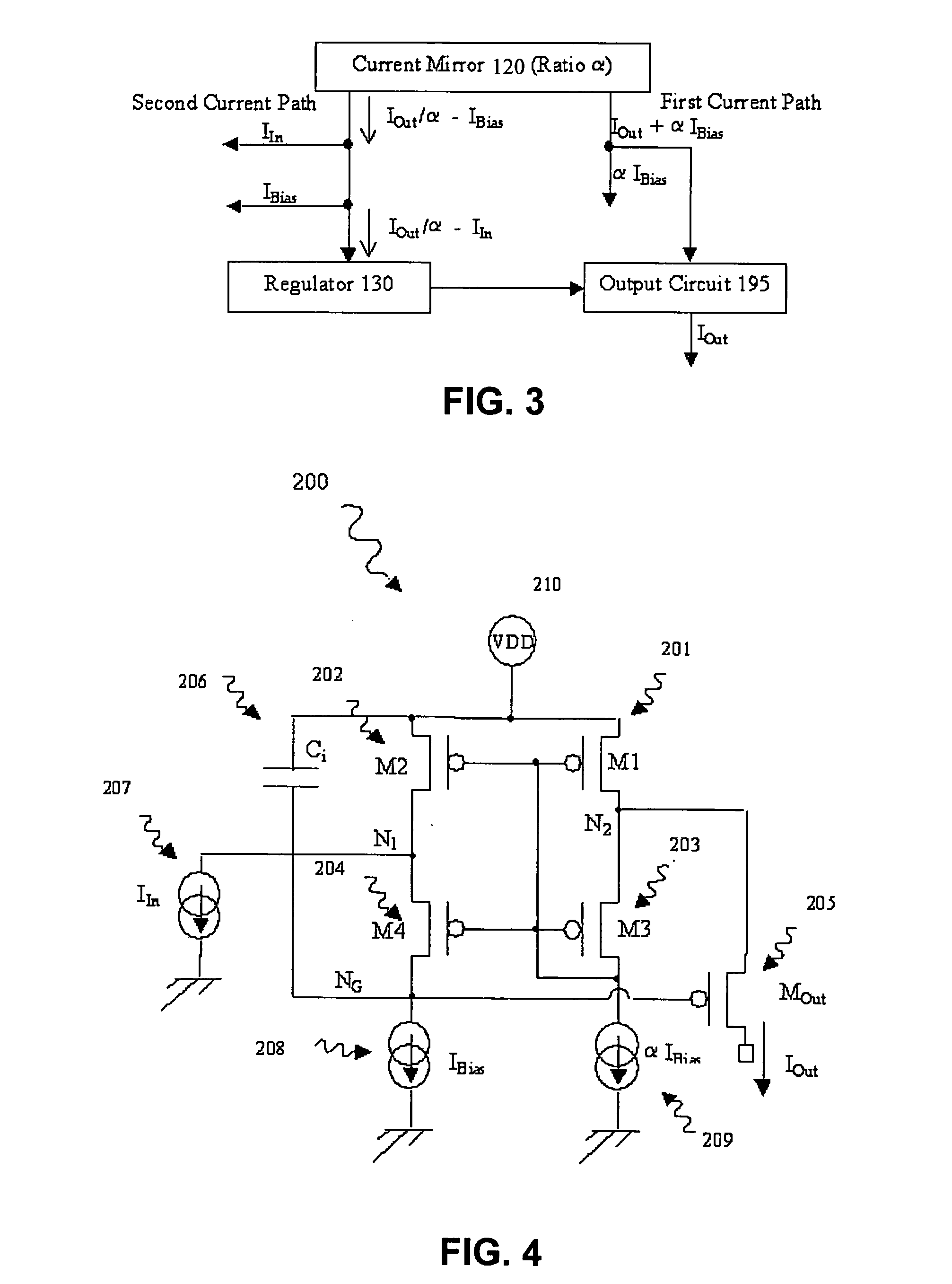
[0006] The present invention can provide one or more of the following advantages compared with known devices: a higher output resistance at low frequency, a higher dynamic range at constant compliance and precision, i.e. that the ratio of output current to input current is relatively independent of the operating conditions, the design is not determined by specific properties of the transistors, e.g. the sub-threshold properties of a transistor to sense variations of the output current, a reduction in the number of components, e.g. one current mirror instead of two.
[0020] Another such feature is the regulator having an integral action or control function, i.e. making an integration of a signal over time. This can be implemented by a capacitor. This can provide better regulation.

Problems solved by technology

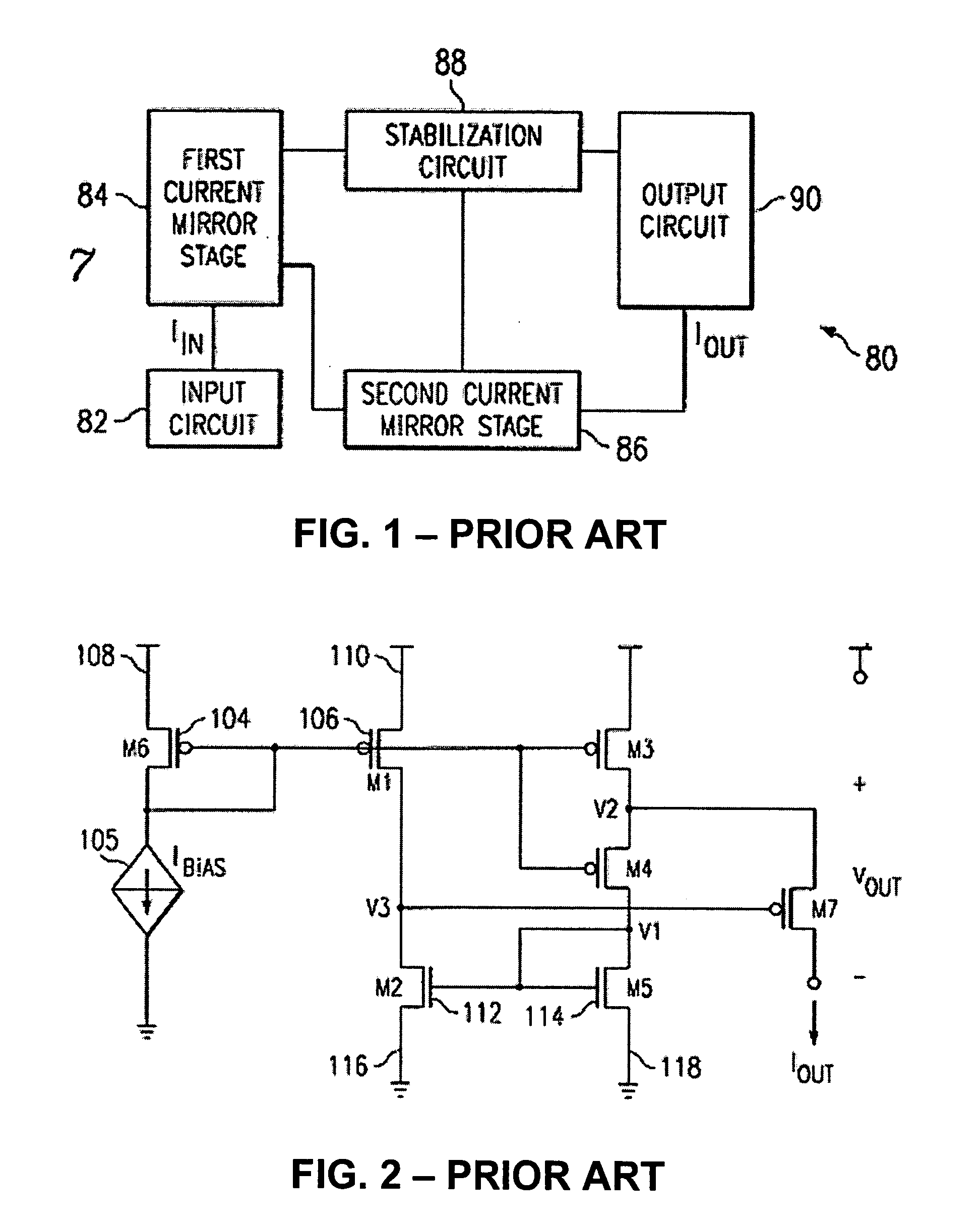
But this and other prior art solutions have various disadvantages including lack of headroom, constrained operating characteristics, poor dynamics, and / or the need for OTAs which increase the surface of silicon (or in other words the transistor count) as well as the power dissipation.
System theory demonstrates that such a regulator used in the considered circuit can never achieve astatism of order 1.

Method used


Image

  • Regulated current mirror
  • Regulated current mirror
  • Regulated current mirror

Examples


Embodiment Construction

[0032] The present invention will be described with respect to particular embodiments and with reference to certain drawings but the invention is not limited thereto but only by the claims. Any reference signs in the claims shall not be construed as limiting the scope of the invention. The drawings described are only schematic and are non-limiting. In the drawings, the size of some of the elements may be exaggerated and not drawn on scale for illustrative purposes.

[0033] The terms first, second, third and the like in the description and in the claims, are used for distinguishing between similar elements and not necessarily for describing a sequential or chronological order. It is to be understood that the terms so used are interchangeable under appropriate circumstances and that the embodiments of the invention described herein are capable of operation in other sequences than described or illustrated herein.

[0034] Furthermore, the terms top, bottom, over, under and the like in the...


PUM


Abstract

A regulated mirror current source circuit has an output transistor, a regulator for controlling the output circuit, and a current mirror having two or more current paths. The first path of the mirror is coupled in series with a current path of the output circuit, and the second path is coupled to the regulator, to provide feedback. The feedback can provide better precision, or reduced component area. The circuit can include cascode transistors, and the regulator can have integral control. The output transistor gate-source voltage is overdriven to reduce “on” resistance of the output transistor. When the output transistor is a high voltage transistor, its area can be reduced without sacrificing compliance.

Description

FIELD OF THE INVENTION [0001] This invention relates to regulated current mirror circuits and to integrated semiconductor devices having such circuits and methods of making and operating the same. DESCRIPTION OF THE RELATED ART [0002] It is known to use current mirror circuits for various applications including current sources. These can be used for biasing of differential pairs, or for use in transconductance amplifiers and high speed digital receivers for example. There are many other applications of mirror circuits in analog low voltage or high voltage circuitry. As explained in U.S. Pat. No. 6,433,528, current mirrors replicate at their outputs the currents present at their inputs. There are many variations of the basic current mirror including regular cascode, high-swing cascode, regulated cascode, low voltage current, and active-input regulated cascode mirrors. U.S. Pat. No. 6,433,528 shows in FIG. 6 an example of a regulated cascode current mirror circuit, which uses an opera...

Claims


Application Information

Patent Timeline
Patent Type & Authority Applications(United States)
IPC IPC(8): G05F3/16
CPCG05F3/262
Inventor PLOJHAR, JAN
Owner AMI SEMICON BELGIUM
Learn More