Inertial voice type coil actuator

Inactive Publication Date: 2006-06-01
REVOLUTION ACOUSTICS
View PDF13 Cites 59 Cited by
  • Summary
  • Abstract
  • Description
  • Claims
  • Application Information

AI Technical Summary

Benefits of technology

[0017] A fifth objective is to provide an inertial voice coil actuator equipped with means to quickly and removably affix the voice coil actuator to various sur

Problems solved by technology

These inertial type voice coil transducers are built upon magnetic circuit designs that have classically been used for conventional cone type loudspeakers and not optimized for driving soundboard type structures.
Some manufacturers have utilized higher energy rare earth based magnets such as Neodymium, but this magnetic architecture is not optimized for the characteristics of these magnets.
These types of electrodynamic transducers are plagued with well known problems of low power handling, limited frequency response, high levels of sound distortion, substantial size and mass, mechanical complexity and high production costs.
However, these prior art voice coil ac

Method used


Image

  • Inertial voice type coil actuator
  • Inertial voice type coil actuator
  • Inertial voice type coil actuator

Examples


third embodiment

[0072] This third embodiment as shown in FIGS. 8-13 gives full consideration to the sequencing used in standard wall construction, whereby the retainer 200 is mounted to stud member 202 after the wall framing is fabricated. Once retainer 200 is affixed, voice coil actuator assembly 90 is inserted into retainer 200 following the center axis of the voice coil actuator assembly 90 as shown in FIG. 9 and FIG. 10. Receiving means 210 is included to secure said voice coil actuator assembly. Said means 210 may be as simple as a “c” opening in which said actuator is placed. Receiving means 210 as shown in FIGS. 8-13 comprises a receiving cavity, a plurality of horizontal rib guides 209 and 211, as well as vertical ribs 208. Said voice coil actuator further comprises at least one electrical contact 214. Said retainer 200 further comprises at least one sprung electrical contact 215. As the voice coil actuator is inserted into receiving cavity 210, it is slidably guided by horizontal rib guide...

fourth embodiment

[0078] A fourth embodiment is shown best in FIGS. 14 and 15. In FIG. 14 the integrated mounting apparatus includes output disk 112 comprising an annular hole 310. Said output disk 112 is attached to a soundboard member 306 by means of a clamping mechanism 302. Co-axially located with and generally covering the annular hole 310 of the output disk 112 is at least one high frequency speaker element 301. Said at least one high frequency speaker element 301 is mounted in such a manner that the acoustic output side 312 of each said speaker element 301 is facing the preferred direction for transmitting the acoustic response of the high frequency element of the system. A vibration isolation pad 304 may be positioned to be in communication with said output disk 112 and with each said high frequency element 301. The pad 304 will reduce the dynamic mass experienced by the voice coil actuator and minimize the structural vibration each high frequency speaker element 301.

[0079] Each said at least...


PUM


Abstract

The present invention provides an intertial-type voice actuator that includes a magnetic flux conductive material core with a continuous channel. The channel has antifringing groove. The actuator employs a radially polarized cylindrical magnet spaced in the channel to form a magnetic gap and a conductive coil positioned at least partially in the gap. A multi-component suspension system provides high quality sound using an antifriction bearing, a viscous magnetic fluid, and a spider suspension. The inertial-type actuator is completed by an integrated mounting apparatus. In one embodiment, a receiver and an output disk are interlocked by helical wedges and the actuator is mounted on a soundboard. In another embodiment, a special receiving cavity is attached to a wall stud for intrawall installation. The cavity is equipped with longitudinal electrical contacts so that the actuator can move and still be connected. After the actuator is inserted, the wall covering is installed.

Description

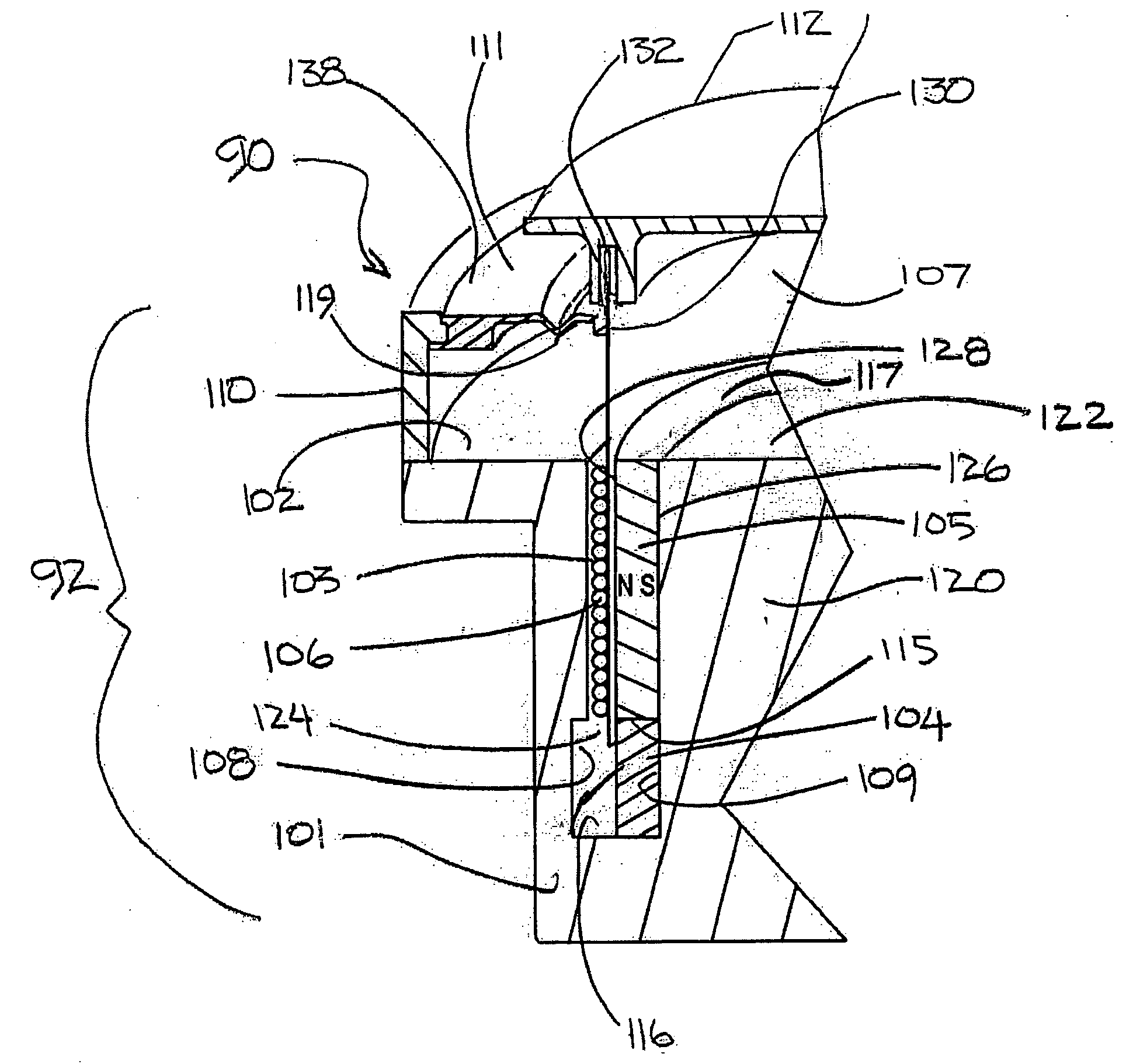
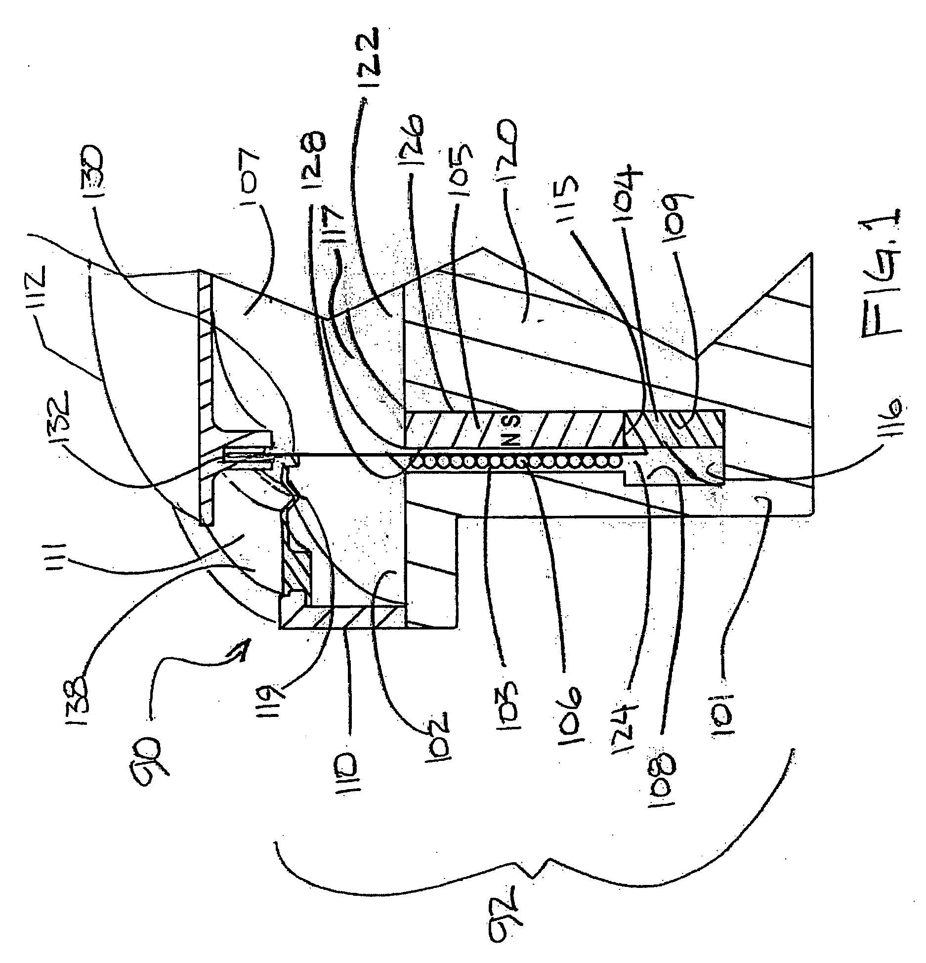
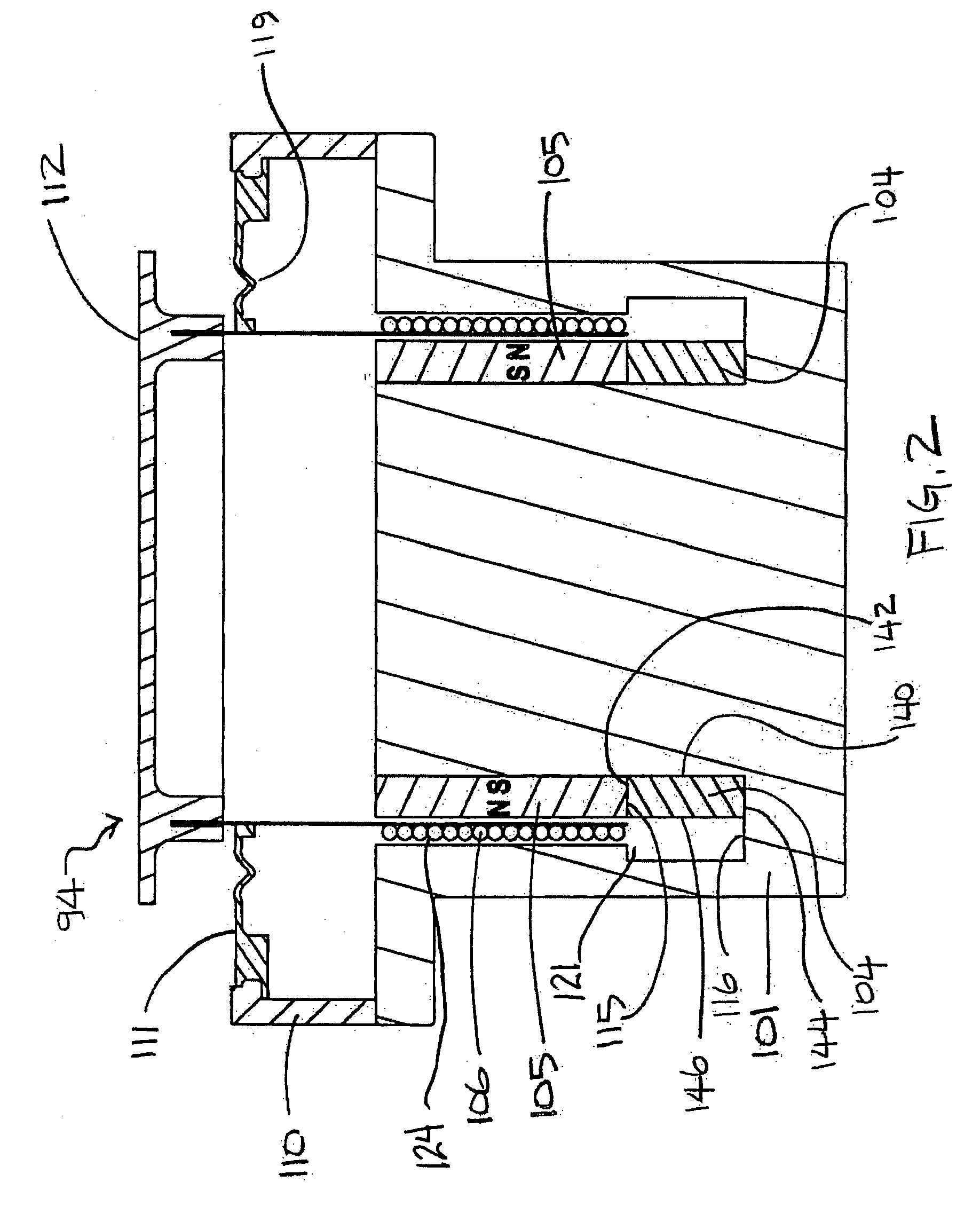
BACKGROUND OF THE INVENTION [0001] 1. Field of the Invention [0002] The present invention relates generally to inertial type voice coil actuators capable of converting energy between electrical and mechanical form and, more particularly, to an inertial type voice coil actuator that utilizes radially polarized biasing magnets and a multicomponent suspension for alignment of the moving coil. [0003] 2. Description of the Prior Art [0004] Inertial voice coil actuators have been used in the past to acoustically stimulate semi-rigid structures to radiate sound. In this application, voice coil actuators have been attached to structures that are relatively large to act as a soundboard such as a wall in a room, where the wall of the room, when acoustically driven radiates sound. As is well known in the art, the force generated by an electrodynamic transducer is a product of the current, I, length of coil wire, L and flux density, B so that F=iL{circle around (×)}B. The length of the coil wir...

Claims


Application Information

Patent Timeline
IPC IPC(8): H04R9/06H04R1/00
CPCH04R7/20H04R9/025H04R9/043
Inventor VINCENT, STEPHEN SAINTKATZ, ROBERTDUCHESNE, SYLVAIN
Owner REVOLUTION ACOUSTICS
Why Eureka
Try Eureka