Method and apparatus for decreasing marine vessel power plant exhaust temperature

a technology for marine vessels and power plants, applied in marine propulsion, vessel construction, offensive equipment, etc., can solve the problems of substantial, undesirable thermal signals of marine vessels, and achieve the effect of less fuel, reduced fuel reserve requirements, and same rang

Inactive Publication Date: 2006-06-01
CARRIER CORP
View PDF27 Cites 19 Cited by
  • Summary
  • Abstract
  • Description
  • Claims
  • Application Information

AI Technical Summary

Benefits of technology

[0010] The range of a marine vessel that burns liquid fossil fuel within its power plant is typically dictated by the fuel reserve it can carry. In most modem marine vessels, a portion of the fuel reserve is devoted to running a power plant that generates electrical energy. Hence, both the propulsion needs and the electrical energy needs draw on the fuel reserve. The present method and apparatus decreases the fuel reserve requirements by generating electricity using waste heat generated by the power plant of the vessel rather than fossil fuel. Hence, the vessel is able to carry less fuel and have the same range, or carry the same amount of fuel and have a greater range.
[0011] The present method and apparatus also provide advantages with respect to the stability of the vessel. For example, the present method and apparatus produces electrical energy via waste heat. Conventional marine systems produce electrical energy by consuming liquid fuel. As the fuel is depleted, the buoyancy characteristics of the vessel are changed. The weight of the present apparatus, on the other hand, remains constant and thereby facilitates stability control of the vessel. In addition, the weight of the present apparatus can be advantageously positioned within the vessel to optimize the stability of the vessel.
[0012] The stability of the vessel is also improved by the smaller exhaust duct, which is enabled by the present invention. The smaller exhaust duct decreases the weight of vessel components disposed above the center of gravity of the vessel, thereby increasing the stability of the vessel.

Problems solved by technology

A problem with releasing thermal energy directly to the environment is that the marine vessel emits a substantial, undesirable thermal signal.

Method used


Image

  • Method and apparatus for decreasing marine vessel power plant exhaust temperature
  • Method and apparatus for decreasing marine vessel power plant exhaust temperature
  • Method and apparatus for decreasing marine vessel power plant exhaust temperature

Examples


Embodiment Construction

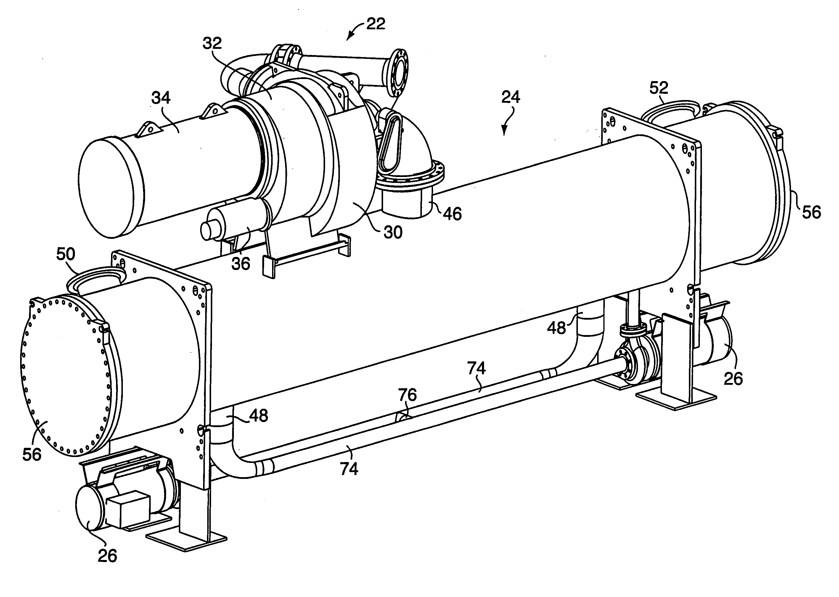
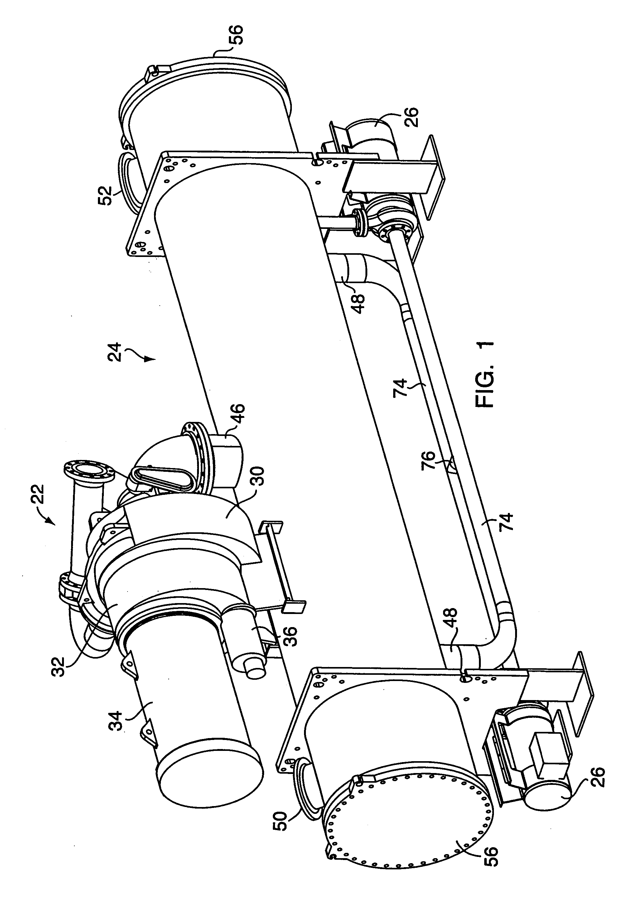
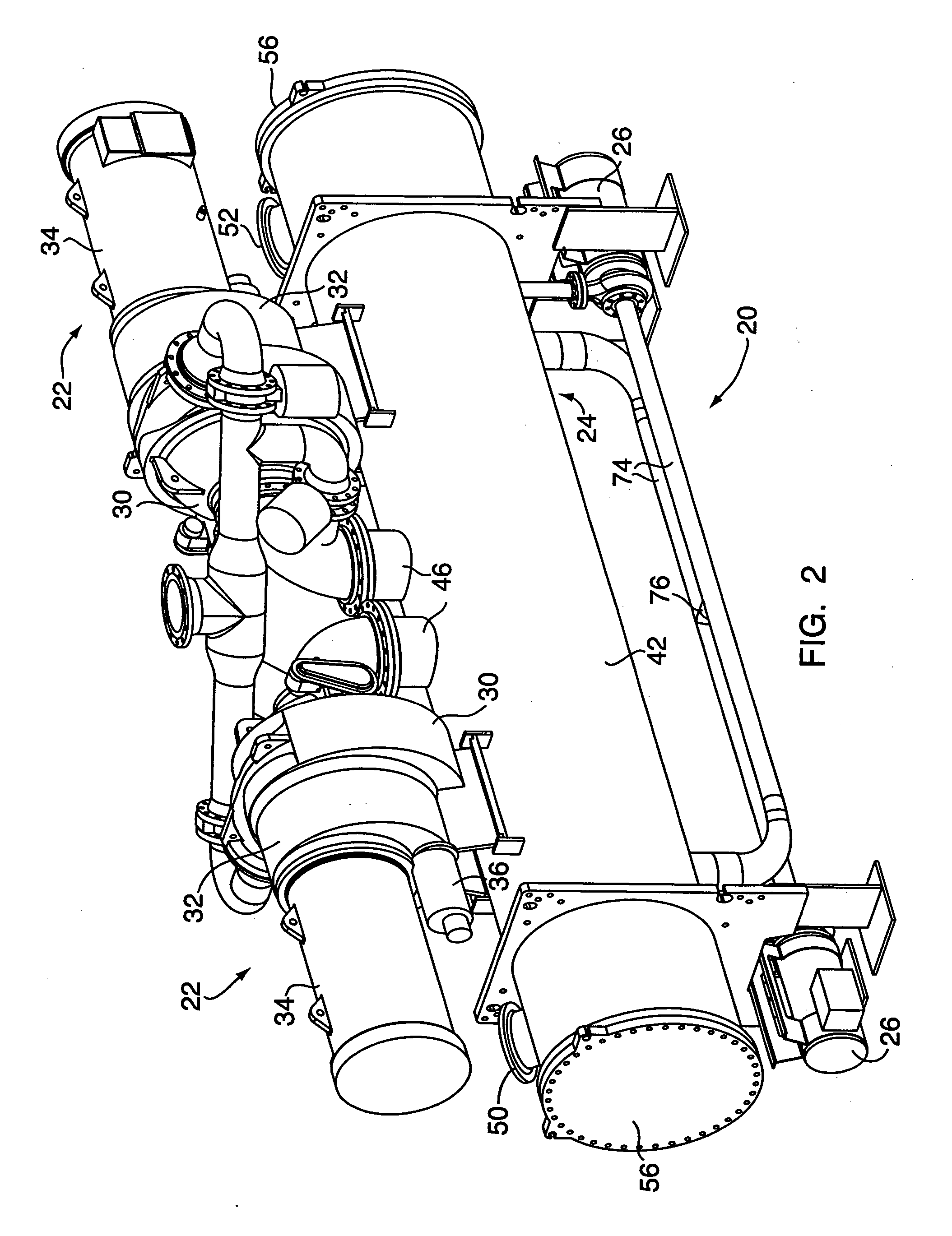
[0025] Referring to FIGS. 1-6, the present method and apparatus for reducing the exhaust temperature of a marine vessel power plant includes providing an organic Rankine cycle (ORC) device 20 for waste heat utilization. The ORC device 20 includes at least one of each of the following: 1) a turbine coupled with an electrical generator (together hereinafter referred to as the “turbo-generator 22”); 2) a condenser 24; 3) a refrigerant feed pump 26; 4) an evaporator 28; and 5) a control system. The ORC device 20 is preferably a closed “hermetic” system with no fluid makeup. In the event of leaks, either non-condensables are automatically purged from the device 20 or charge is manually replenished from refrigerant gas cylinders.

[0026] The ORC device 20 uses a commercially available refrigerant as the working medium. An example of an acceptable working medium is R-245fa (1,1,1,3,3, pentafluoropropane). R-245fa is a non-flammable, non-ozone depleting fluid. R-245fa has a saturation temper...


PUM


Abstract

According to the present invention, a method and apparatus for generating power aboard a marine vessel is provided. The method comprises the steps of: (a) providing a Rankine Cycle device that includes at least one of each of an evaporator, a turbo-generator that includes a turbine coupled with an electrical generator, a condenser, and a refrigerant feed pump; (b) disposing the one or more evaporators within an exhaust duct of a power plant of the marine vessel; (c) operating the power plant; and (d) selectively pumping refrigerant through the Rankine Cycle device, wherein refrigerant exiting the evaporator powers the turbine, which in turn powers the generator to produce power.

Description

BACKGROUND OF THE INVENTION [0001] 1. Technical Field [0002] The present invention relates to methods and apparatus for infrared suppression in general, and to methods and apparatus for decreasing the exhaust temperature of a marine vessel power plant in particular. [0003] 2. Background Information [0004] Marine power plants produce exhaust products typically in a temperature range of 350-1800° F. In most applications, the exhaust products are passed through a sizable duct (typically referred to as a “stack”) and released to the environment. Once released to the environment, the thermal energy dissipates. A problem with releasing thermal energy directly to the environment is that the marine vessel emits a substantial, undesirable thermal signal. [0005] What is needed is a method and apparatus for suppressing the thermal signal of a marine vessel. SUMMARY OF THE INVENTION [0006] According to the present invention, a method and apparatus for decreasing the exhaust temperature of a mar...

Claims


Application Information

Patent Timeline
Patent Type & Authority Applications(United States)
IPC IPC(8): B63H11/103
CPCB63G13/02B63H20/245
Inventor SUNDEL, TIMOTHY NEIL
Owner CARRIER CORP
Why Eureka
Try Eureka