Apparatus and method for three-dimensional measurement and program for allowing computer to execute method for three-dimensional measurement

Inactive Publication Date: 2006-06-01
OLYMPUS CORP
View PDF17 Cites 8 Cited by
  • Summary
  • Abstract
  • Description
  • Claims
  • Application Information

AI Technical Summary

Benefits of technology

[0017] The present invention is made in view of the above circumstances. It is an object of the present invention to provide a three-dimensional measuring apparatus which is compact and helps construct an excellent system and which enables measurement

Problems solved by technology

However, in contrast, the size of the shadow (dead angle) of the object to be measured increases to widen a non-measurable range.
Further, within the range in which the lattice pattern is not projected, the height cannot be correctly calculated because information on the lattice pattern is not obtained.
As a result, an optical path is extended, and the lattice pattern projecting device poses optical problems such as an insufficient quantity of peripheral light and an eclipse.
Another problem is a limitation to the system.
Moreover, the increased size of the intermediate lens barrel raises eye points.
Furthermore, the angle at which a lattice pattern is projected on a sample is limited by the inward angle of the stereomicroscope.
This precludes the obtainment of measurement accuracy corresponding to the sample.
In general, measurement accuracy increases consistently with the projection angle α. However, owing to the relatively small inward angle of the stereomicroscope, the measurement accuracy is not expected to be significantly improved.
The apparatus thus has

Method used


Image

  • Apparatus and method for three-dimensional measurement and program for allowing computer to execute method for three-dimensional measurement
  • Apparatus and method for three-dimensional measurement and program for allowing computer to execute method for three-dimensional measurement
  • Apparatus and method for three-dimensional measurement and program for allowing computer to execute method for three-dimensional measurement

Examples


first embodiment

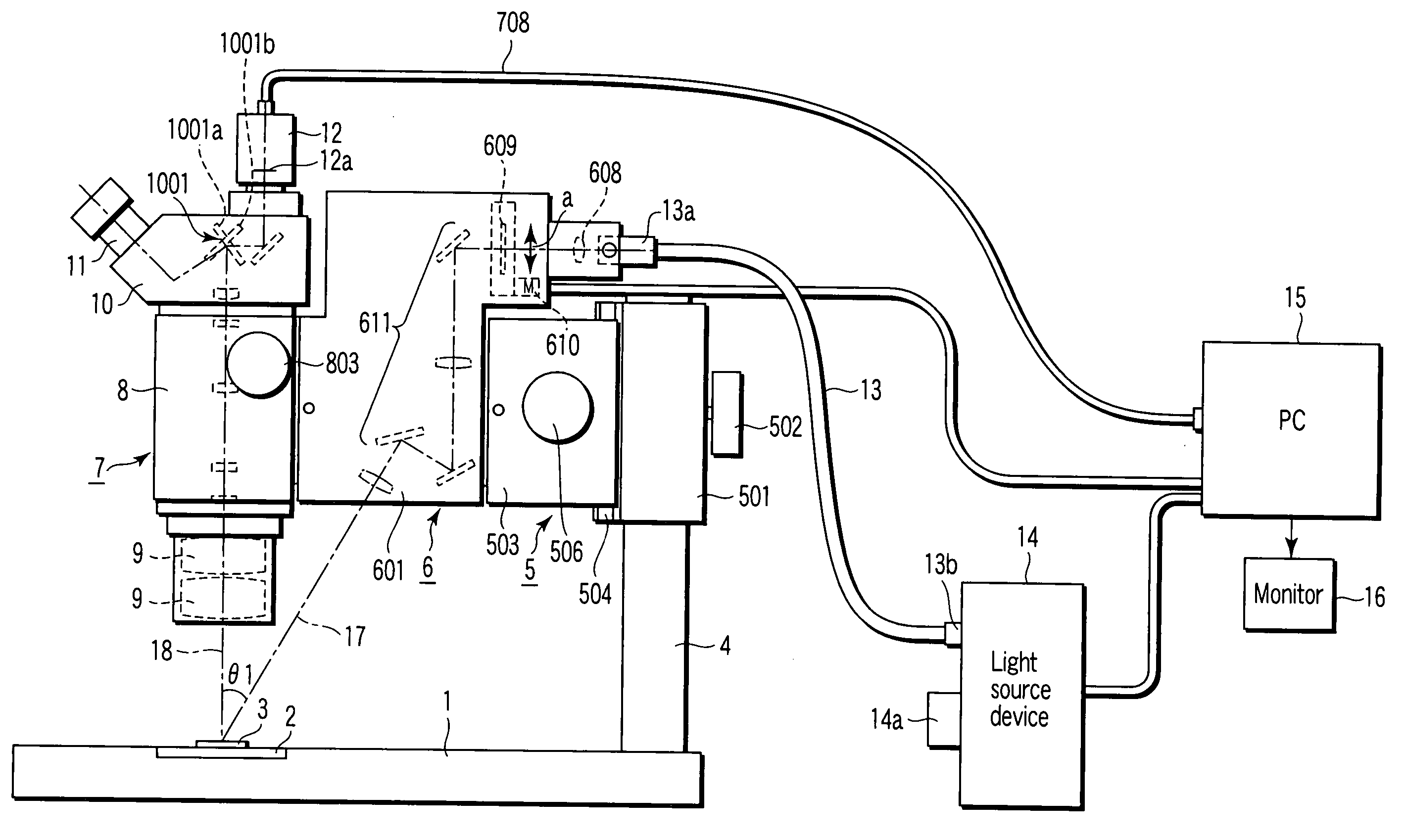
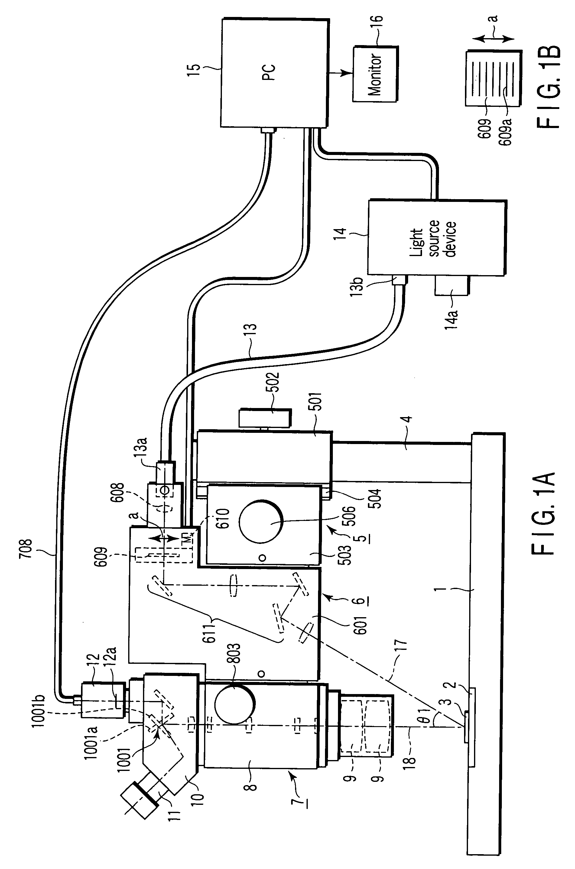
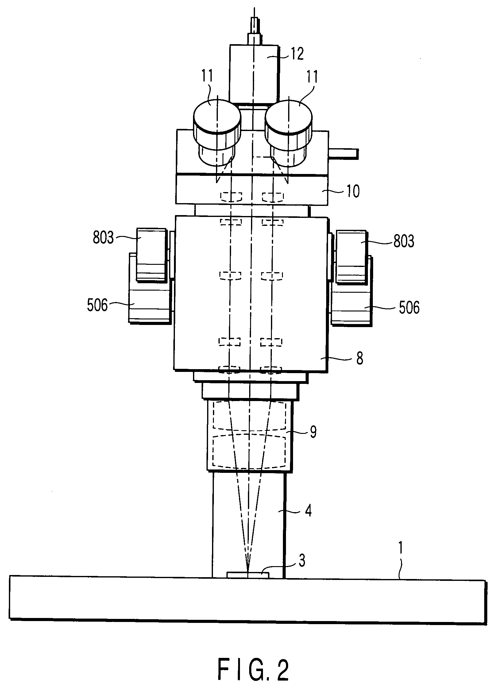
[0049]FIGS. 1A and 2 show a side view and a front view of a schematic configuration of a three-dimensional measuring apparatus in accordance with the present invention.

[0050] In FIG. 1A, a stage 2 is provided on a base 1. A sample 3 is placed on the stage 2.

[0051] A pole 4 is uprightly provided on the base 1. A focusing device 5 is provided on the pole 4. The focusing device 5 is provided with a lattice pattern projecting device 6 that projects a lattice pattern. The lattice pattern projecting device 6 is provided with a stereomicroscope 7.

[0052]FIGS. 3A, 3B, 3C, and 3D show a schematic configuration of the focusing device 5.

[0053]FIG. 3A is a side view the focusing device 5. FIG. 3B is a top view of the focusing device 5. FIG. 3C is a bottom view of the focusing device 5. FIG. 3D is a front view of the focusing device 5.

[0054] In FIGS. 3A to 3D, a hole portion 501a is formed in a focusing device main body 501 so that the pole 4 is inserted through the hole portion 501a. A fixin...

second embodiment

[0095] Now, with reference to the drawings, description will be given of a second embodiment in accordance with the present invention.

[0096] The same members as those in the first embodiment have the same reference numerals and their detailed description is omitted.

[0097] FIGS. 6 to 14 show a three-dimensional measuring apparatus employing the lattice pattern projection method according to the second embodiment of the present invention. FIGS. 6 and 7 are a side view and a front view of a schematic configuration of a three-dimensional measuring apparatus in accordance with the second embodiment of the present invention. FIG. 8 is a right side view of the lattice pattern projecting device. FIG. 9 is a partly sectional right side view of the lattice pattern projecting device. FIG. 10 is a sectional view taken along line AA′ in FIG. 9. FIG. 11 is a sectional view taken along line BB′ in FIG. 9. FIG. 12 is a sectional view taken along line AA′ in FIG. 9. FIG. 13 is a sectional view take...

third embodiment

[0136] Now, with reference to the drawings, description will be given of a third embodiment in accordance with the present invention.

[0137] The same members as those in the first and second embodiments have the same reference numerals and their detailed description is omitted.

[0138] FIGS. 15 to 20 show a three-dimensional measuring apparatus employing the lattice pattern projection method according to the third embodiment of the present invention. FIG. 15 is a side view of a schematic configuration of a three-dimensional measuring apparatus in accordance with the third embodiment of the present invention. FIG. 16 is a front view of the schematic configuration of the three-dimensional measuring apparatus in accordance with the third embodiment of the present invention. FIG. 17 is a partly sectional right side view of the lattice pattern projecting apparatus (the sectional portion is taken along line CC′ shown in FIG. 18). FIG. 18 is a top view of the lattice pattern projecting appar...


PUM


Abstract

The present invention has a three-dimensional apparatus including a lattice pattern placed in an optical path and having a slit-like light transmitting portion formed of pitches set at fixed intervals, and a projecting optical system that projects a lattice pattern image formed by the lattice pattern on the sample so that the image is inclined at a predetermined angle. A lattice pitch is determined on the basis of set parameters including the magnification of an observing system. A pattern is formed by the lattice pitch. The pattern is used to pick up a deformed lattice pattern image using a TV camera. An image of each position is acquired while shifting the lattice pattern over several levels. A phase is determined. A height is then determined using the difference between the phase and a basic phase corresponding to a pre-provided magnification or the like. The height is then displayed.

Description

CROSS-REFERENCE TO RELATED APPLICATIONS [0001] This application is based upon and claims the benefit of priority from prior Japanese Patent Applications No. 2004-342497, filed Nov. 26, 2004; No. 2004-344192, filed Nov. 29, 2004; and No. 2005-271761, filed Sep. 20, 2005, the entire contents of all of which are incorporated herein by reference. BACKGROUND OF THE INVENTION [0002] 1. Field of the Invention [0003] The present invention relates to a three-dimensional measuring apparatus that uses a lattice pattern projection method for measuring the three-dimensional shape of a sample surface to obtain for example, information on the height of the sample, a method for three-dimensional measurement employing the lattice pattern projection method, and a program for allowing a computer to execute the method for three-dimensional measurement. [0004] 2. Description of the Related Art [0005] A lattice pattern projection method is conventionally known as a means for measuring the surface shape o...

Claims


Application Information

Patent Timeline
IPC IPC(8): G01B11/22
CPCG01B9/04G02B21/22G02B21/365
Inventor UTSUGI, HIRONORIRYU, GOOBUCHI, HIDEKI
Owner OLYMPUS CORP
Why Eureka
Try Eureka