Current prediction in a switching power supply

a technology of switching power supply and current prediction, which is applied in the direction of ac network voltage adjustment, efficient power electronics conversion, electric variable regulation, etc., to achieve the effect of less expensiv

Active Publication Date: 2006-06-08
ELECTROVAYA
View PDF19 Cites 60 Cited by
  • Summary
  • Abstract
  • Description
  • Claims
  • Application Information

AI Technical Summary

Benefits of technology

[0020] (4) a less expe...

Problems solved by technology

For example, some or all of the discussed publications may not be sufficiently early in time, may not reflect subject mat...

Method used


Image

  • Current prediction in a switching power supply
  • Current prediction in a switching power supply
  • Current prediction in a switching power supply

Examples


Embodiment Construction

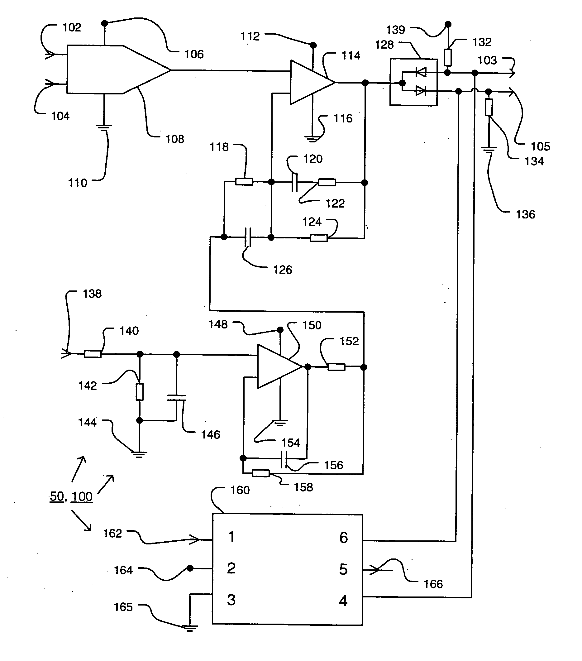
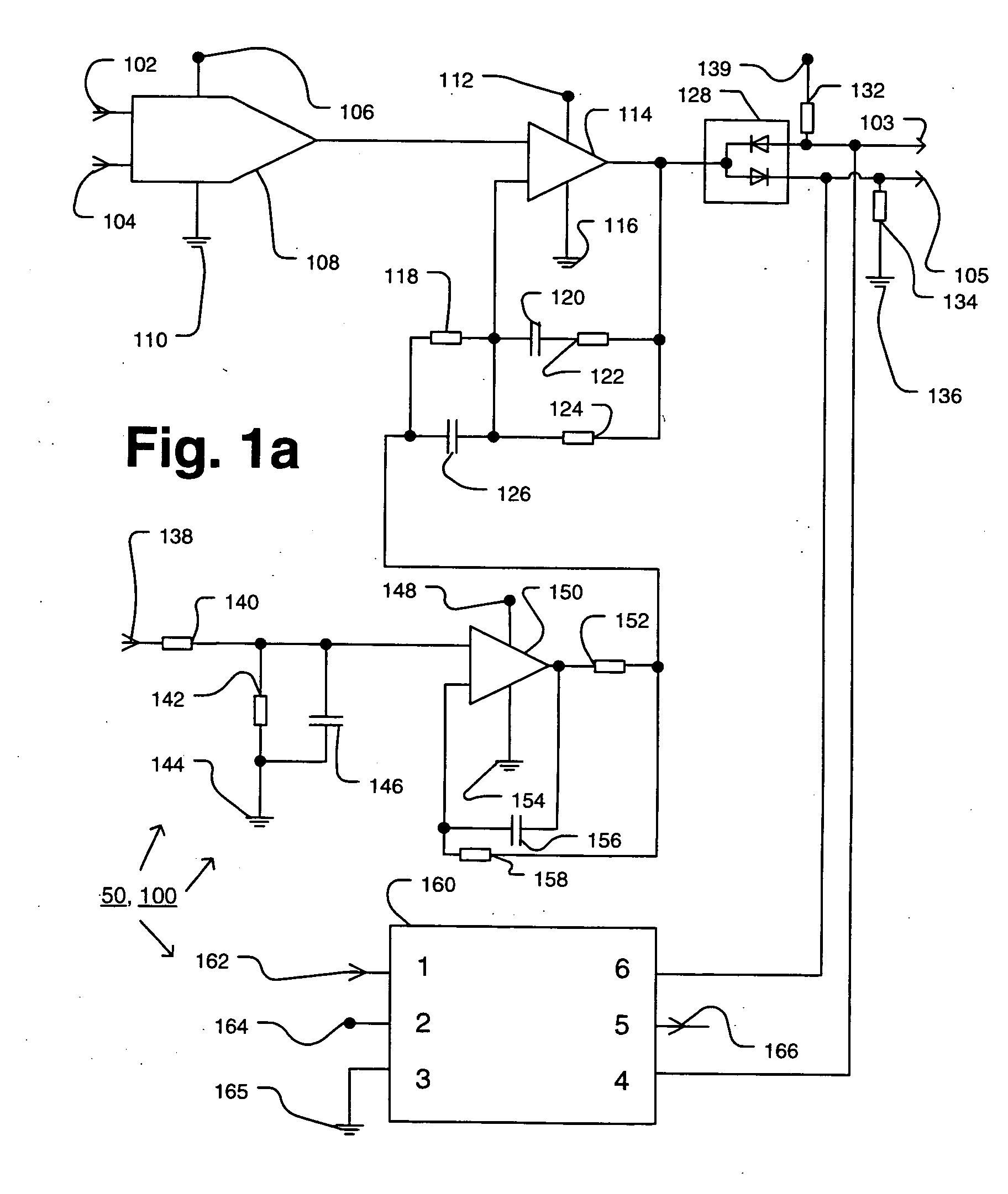
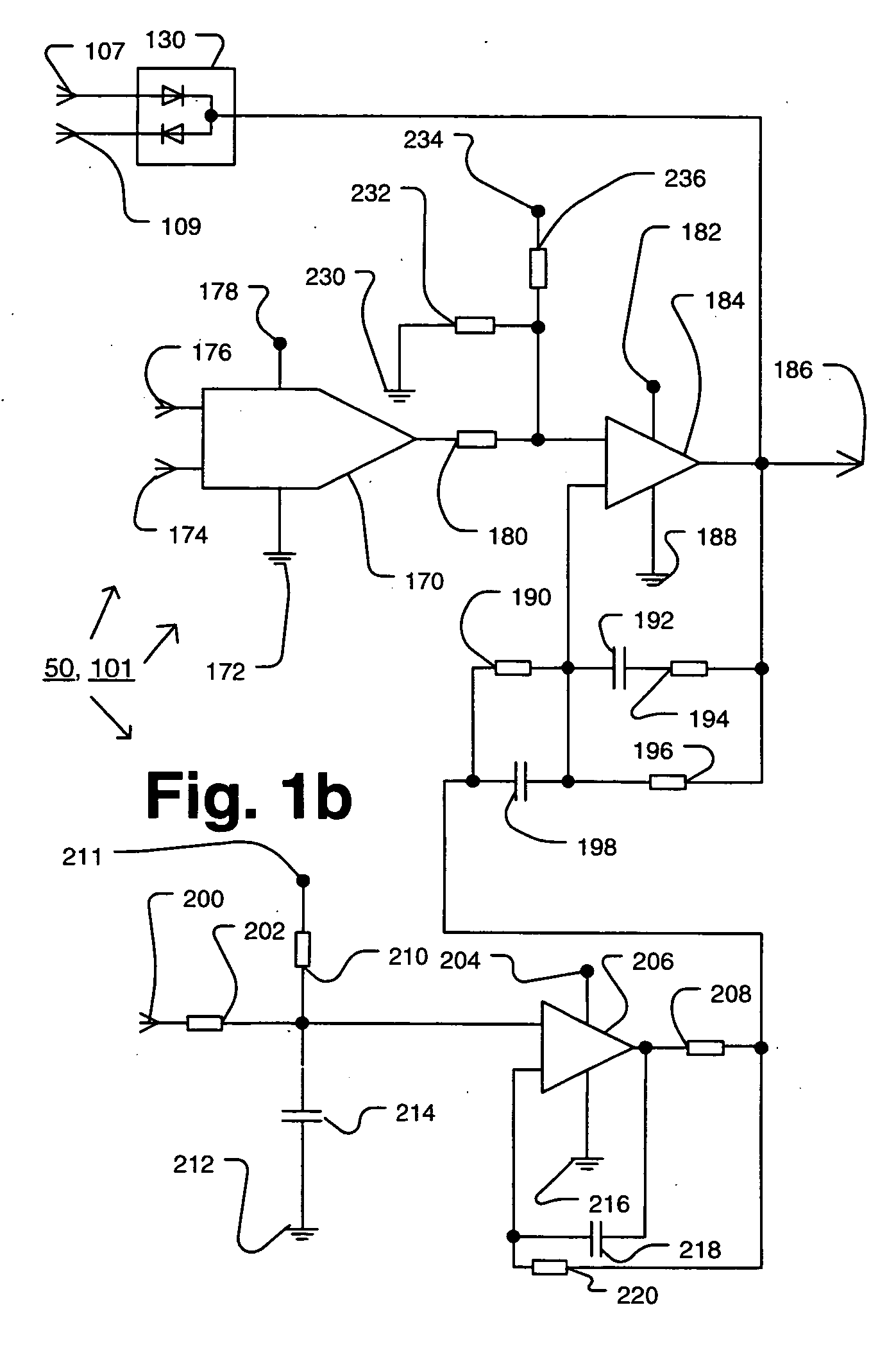
[0072] The following exemplary embodiment(s) of a switching power supply will be given in the context of a switching power supply used in a battery device. More particularly, the battery device (not separately shown in the Figs.) includes the switching power supply and rechargeable electrochemical cells (preferably lithium ion or lithium polymer cells) in a housing. One or more jacks at an external surface of the housing allow external devices to be electrically connected and disconnected from the switching power supply. Because it is electrically interposed between the external device(s) and the electrochemical cells, the switching power supply here controls the charging and discharging of the electrochemical cells. Specifically, an external power source can be connected via a jack to recharge the electrochemical cells when they have been drained of charge. Alternatively (or additionally) an external load can be connected. This external load can then be powered by the electrochemic...


PUM


Abstract

A high efficiency switching power supply including an analog front end, a battery control circuitry portion, a display and equalization circuitry portion, field effect transistor (FET) drivers, an isolated power supply transformer circuitry (and three associated sets of tap circuitry), microcontroller circuitry, oscillator circuitry, overcharge protection circuitry, programmable logic circuitry portion, and a zero current predictor. Overbiasing of the FET power supply switches, and/or other various circuitry features disclosed herein, helps achieve electrical power efficiencies of preferably greater than 95%, even more preferably greater than 98% and even more preferably greater than 99%. Preferably, the switching power supply has one or more of the following: (1) high electrical power efficiency (>95%. >98%, >99%); (2) overbiasing of a gate of a power supply switch; (3) a power supply switch with a low gate capacitance ratio; (4) multiple modes of operation; and (5) current prediction wherein an inductor voltage is used to control a constant current capacitor whose voltage indicates the level of current in the inductor.

Description

RELATED APPLICATION DATA [0001] This application claims any and all applicable benefits based on the following provisional patent application(s): (1) U.S. patent application No. 60 / 592,386 filed on 2 Aug. 2004; (1) U.S. patent application No. 60 / 656,911 filed on 1 Mar. 2005; (2) U.S. patent application No. 60 / 656,889 filed on 1 Mar. 2005; (3) U.S. patent application No. 60 / 656,913 filed on 1 Mar. 2005; (4) U.S. patent application No. 60 / 657,417 filed on 2 Mar. 2005; and (5) U.S. patent application No. 60 / 656,914 filed on 1 Mar. 2005. All of the foregoing patent-related documents are herein incorporated by reference.FIELD OF THE INVENTION [0002] The present invention relates to power supplies and more particularly to high efficiency dc-dc converter switching power supplies. DESCRIPTION OF THE RELATED ART [0003] Power supplies and switching power supplies are well known and conventional. A switching power supply generally includes: (1) an input power signal (see DEFINITIONS section fo...

Claims


Application Information

Patent Timeline
IPC IPC(8): G05F1/10
CPCH02M3/3376H02M2001/0009H02M2001/0048H03K17/08142H03K17/133H03K17/162H03K17/6872Y02B70/1491H02M2001/0058H02M1/0009H02M1/0048H02M1/0058Y02B70/10
Inventor JACOBS, JAMES K.DASGUPTA, SANKARVANDERMEER, DAVID
Owner ELECTROVAYA
Why Eureka
Try Eureka