
Wireless communication system for determining the number of operation stages of interference canceller

Inactive Publication Date: 2006-06-08
NEC CORP
View PDF8 Cites 12 Cited by
  • Summary
  • Abstract
  • Description
  • Claims
  • Application Information

AI Technical Summary

Benefits of technology

[0011] The present invention has been made in view of the above disadvantage relating to the prior art, and an object thereof is to provide a wireless base station apparatus, wireless transceiver and wireless communication system capable of improving the performance thereof, by which processing time can be shortened and communication errors can be reduced.

Problems solved by technology

Therefore, interference between the signals occurs depending on correlation between codes that are allocated by multipath signal or other users' signals.
As a result, signal characteristics are deteriorated as the number of signals is increased.
A first disadvantage of the related art is that the interference canceller has a multistage structure and thereby it takes long time if processing is performed to the last stage.
That is, since data needed to be transmitted and received promptly are also processed to the last stage, it takes long time to complete transmission / reception of the data.
In particular, in the case where a serial interference canceller is used, it takes 100 millisecond or more to complete transmission / reception of data, with the result that a voice communication cannot be made smoothly.
Further, it also takes long time to acquire the SIR of the last stage, with the result that control of the transmission method control is delayed.
As a result, the control did not work well in some cases.
A second disadvantage is that an adaptive modulation function determines an optimum modulation method by which data is transmitted / received according to the SIR of the last stage, so that if a modulation method, coding rate, spread rate, code number, use frequency band and coding method that allow a large number of data to be transmitted in one frame are selected although the data amount is small, it is necessary to transmit dummy data in order to fill the frame with data, thus incurring waste.
Further, a normal communication could not be made with the selected transmission method due to a variation of a state of a transmission path, in some cases.

Method used


Image

  • Wireless communication system for determining the number of operation stages of interference canceller
  • Wireless communication system for determining the number of operation stages of interference canceller
  • Wireless communication system for determining the number of operation stages of interference canceller

Examples


Embodiment Construction

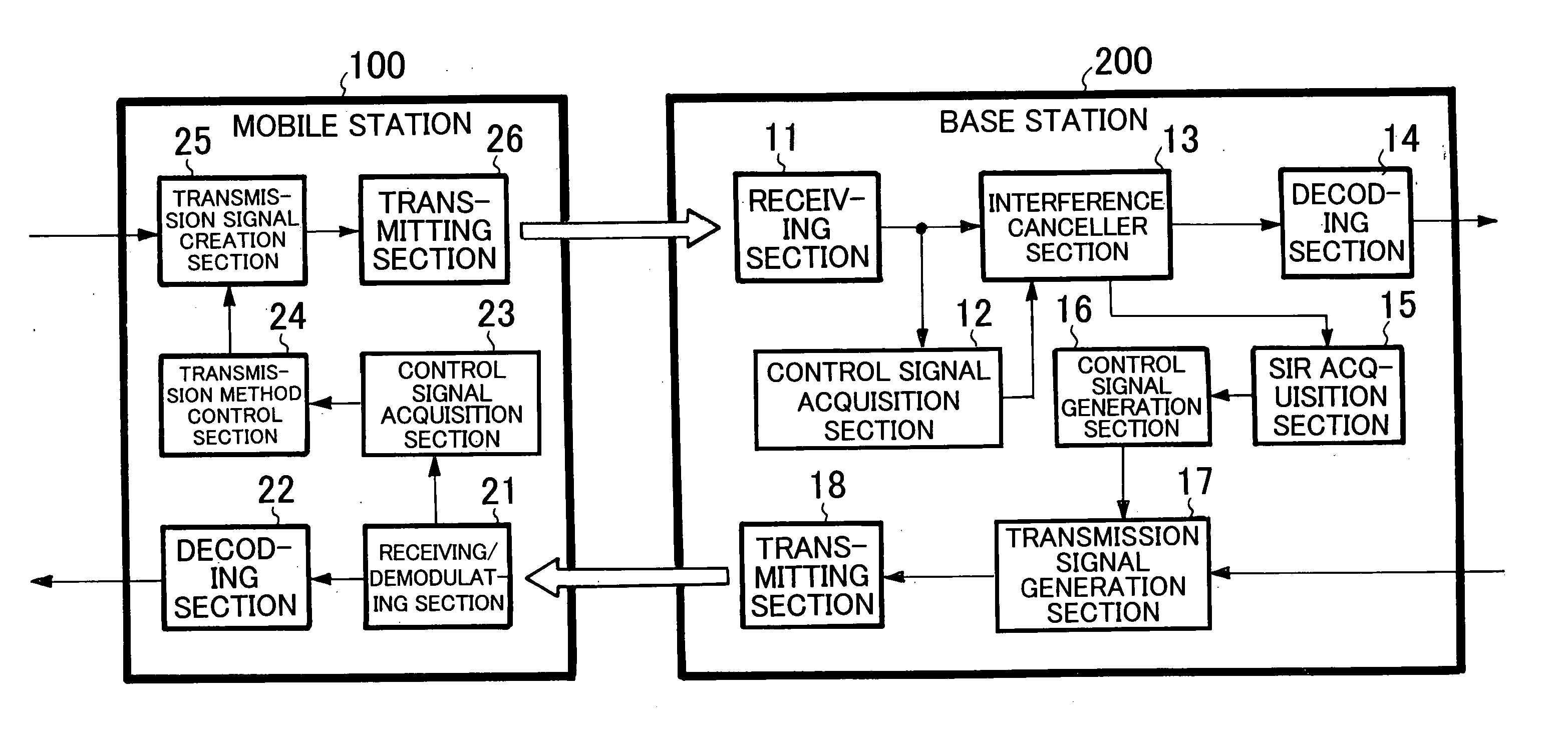
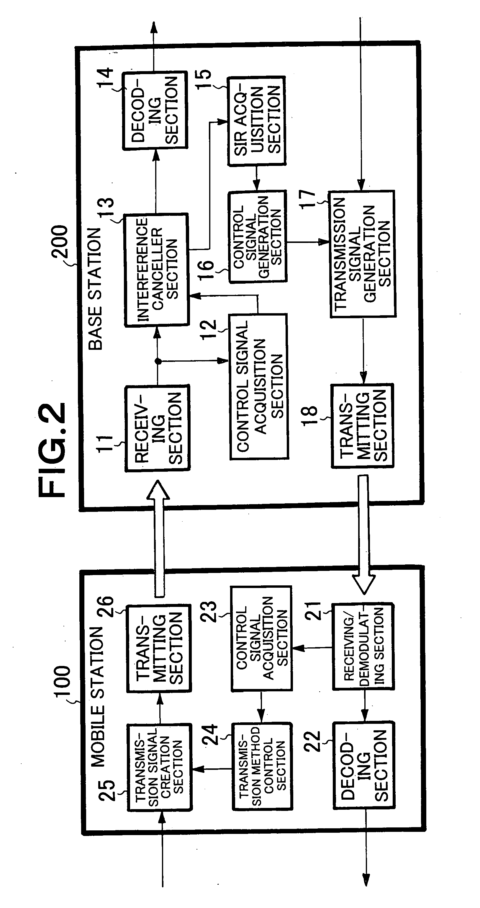
[0024] An embodiment of the present invention will be described in detail below with reference to the accompanying drawings. FIG. 2 is a block diagram showing a configuration of the embodiment of a wireless communication system according to the present invention. The wireless communication system has mobile station 100 for each user and base station 200 capable of communicating with the plurality of mobile stations through a wireless network.

[0025] Firstly, receiving section 11 of the base station 200 receives a spread spectrum signal transmitted from the mobile station 100. Then, a control signal acquisition section 12 acquires a control signal including designation of the number of operation stages of an interference canceller, modulation method, coding rate, spread rate, code number, use frequency band and coding method from the reception signal output from the receiving section 11.

[0026] Interference canceller section 13 removes interference included in the reception signal ou...


PUM


Abstract

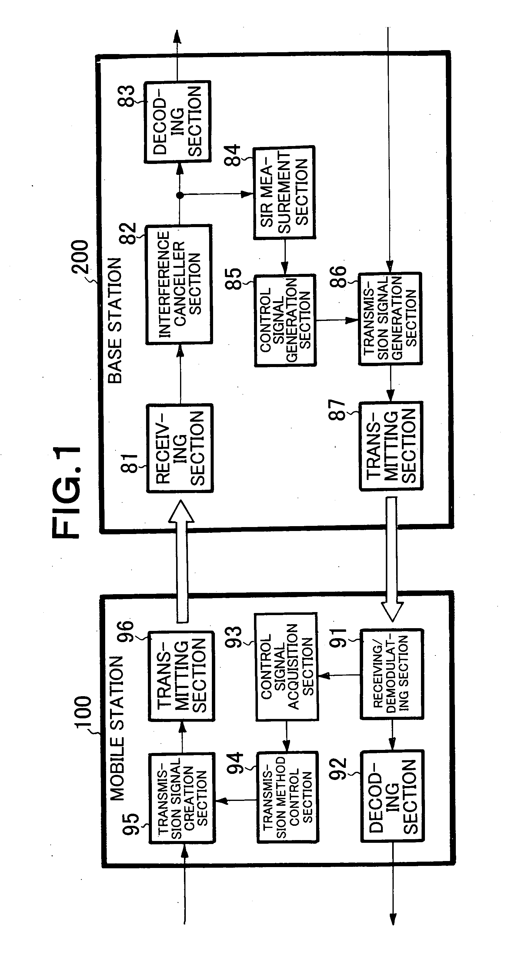
An SIR measurement sections are provided for respective stages of an interference canceller section and SIR values of the respective stages of the interference canceller section is notified to a station of the other end of a communication link to allow the station to determine the number of operation stages of the interference canceller section. The determined number of operation stages is received from the station and the interference canceller section is operated by the determined number of operation stages. This reduces processing time and power consumption. Further, the reduction in processing time makes it possible to perform communication according to an adaptive transmission method in an error-free manner.

Description

BACKGROUND OF THE INVENTION [0001] 1. Field of the Invention [0002] The present invention relates to a wireless base station apparatus, wireless transceiver and wireless communication system and particularly, to an adaptive control method that selects an optimum modulation method and the like for a wireless communication apparatus required in a mobile communication system, a local wireless communication system, or a wireless LAN system. [0003] 2. Description of the Related Art [0004] Conventionally, in a wireless system that performs a Direct Sequence / Code Division Multiple Access (DS / CDMA) communication using a spread spectrum signal, a plurality of signals use a single frequency band at the same time. Therefore, interference between the signals occurs depending on correlation between codes that are allocated by multipath signal or other users' signals. As a result, signal characteristics are deteriorated as the number of signals is increased. To suppress the deterioration of signa...

Claims


Application Information

Patent Timeline
IPC IPC(8): H04B1/707H04B1/10H04B1/40H04B1/7107H04B1/711H04B7/015
CPCH04B1/71075
Inventor KOMATSU, MASAHIRO
Owner NEC CORP
Learn More