Three-dimensional endoscope imaging and display system

a display system and endoscope technology, applied in the field of endoscope systems, can solve the problems of eye strain and fatigue, hardly achieved by monocular vision, and the need for special eyewear, so as to reduce unnecessary contact

Active Publication Date: 2006-06-08
STEREO DISPLAY
View PDF93 Cites 75 Cited by
  • Summary
  • Abstract
  • Description
  • Claims
  • Application Information

AI Technical Summary

Benefits of technology

[0020] The image sensor takes two-dimensional images of an object or scene with one or more focal planes that are shifted by changing the focal length of the variable focal length MMAL. The image processing unit extracts substantially in-focus pixels or areas from each two-dimensional image to generate a corresponding in-focus depthwise image. Based on the known focal length of the two-dimensional image, depth information of the corresponding in-focus depthwise image can be obtained. Each in-focus depthwise image represents a portion of the object having the same image depth. The focal length of the variable focal length MMAL can progressively increase or decrease, or varies in a selected order within a focal length variation range of the variable focal length MMAL such that any portion of the object or scene is imaged substantially in-focus at least once. A set of in-focus depthwise images taken at different focal lengths with a fast imaging rate represents the object or scene at a given moment. The object can remain still or be moving. For the case that the object is moving, the movement of the object can be ignored when the imaging rate is fast enough. The number of in-focus depthwise images representing the object at a given moment (number of depths) depends on the depth resolution requirement, and the refresh rate of the two-dimensional display and the focusing speed of the variable focal length MMAL, and may increase for a better image quality. There are several methods for the image processing unit to generate an all-in-focus image of the object or scene from in-focus depthwise images thereof. Recent advances in both the image sensor and the image processing unit make them as fast as they are required to be. Depth information of each pixel of the all-in-focus image can be obtained in the same way as the depthwise image case. All the processes are achieved within a unit time which is at least persistent rate of the human eye.
[0028] The three-dimensional image display device of the present invention has the following advantages: (1) since the three-dimensional display device actually generates three-dimensional images in the space, the device does not suffer from the disadvantage of prior art device using parallax including imaging difficulties due to considerations for arbitrary distribution of the viewer's position, and binocular disparity due to deviations in the distance between the two eyes, vergence, accommodation, watching by more than one viewers, and the relative position change of the three-dimensional image due to viewer's movement; (2) the cost for providing three-dimensional image data is inexpensive since the data needs only depth information in addition to two-dimensional image information, and thus there is no significant increase in data amount; and (3) the device can be easily converted to a two-dimensional display and vice versa.

Problems solved by technology

Endoscopic procedures require precise hand-eye coordination and minute manipulation, which can be hardly accomplished by monocular vision.
However, a binocular vision system can cause eye-strain and fatigue for prolonged uses, and requires special eye-wear to see three-dimensional images.
Also, it is difficult to design a compact endoscope system without degrading the image quality because the binocular vision system uses multiple camera systems and image delivery systems within the limited space.
In this system, the camera system must be continuously moving to generate three-dimensional effect, which can make inspection and treatment procedures complicated and cause trauma to a patient.
The confocal system can provide a high resolution three-dimensional image with a single camera system, but most of illuminating light is wasted and causes noise problem.
To overcome this, U.S. Pat. No. 6,749,346 to Dickensheets and U.S. Pat. No. 6,563,105 to Seibel use a single optical fiber to scan and collect reflected light, but point by point scanning can lead to a slow image refresh rate.
Conventional endoscope systems usually use a wide field of view; typically, about 70 degree. A wide field of view is useful for viewing an overall internal structure and spotting an area of interest, but it may not provide enough information for diagnosis or treatment because the image produced by the wide field of view tends to suffer from huge distortion and low resolution.
However, it requires complicated macroscopic servo mechanism and yields a slow response time.

Method used


Image

  • Three-dimensional endoscope imaging and display system
  • Three-dimensional endoscope imaging and display system
  • Three-dimensional endoscope imaging and display system

Examples


Embodiment Construction

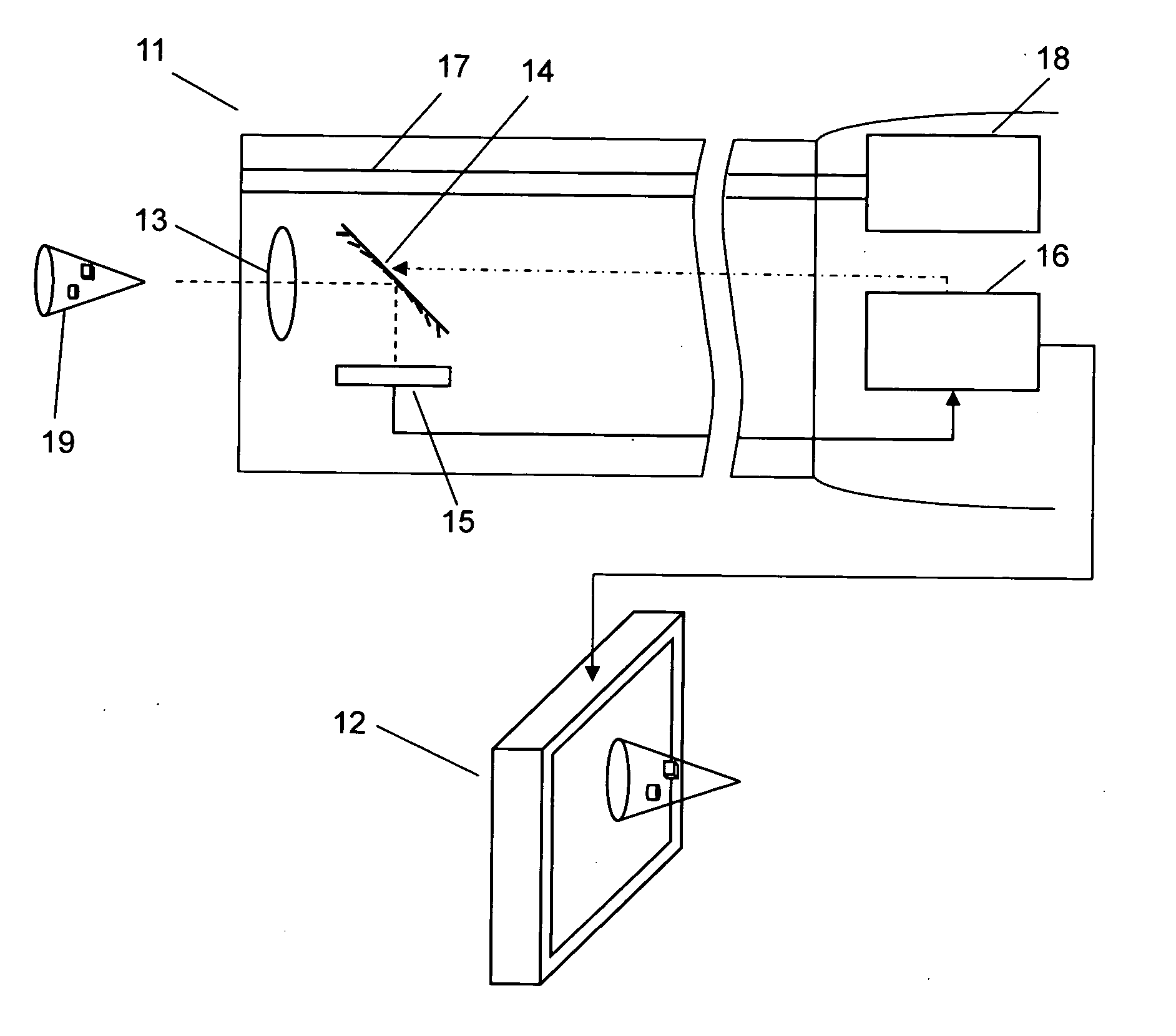
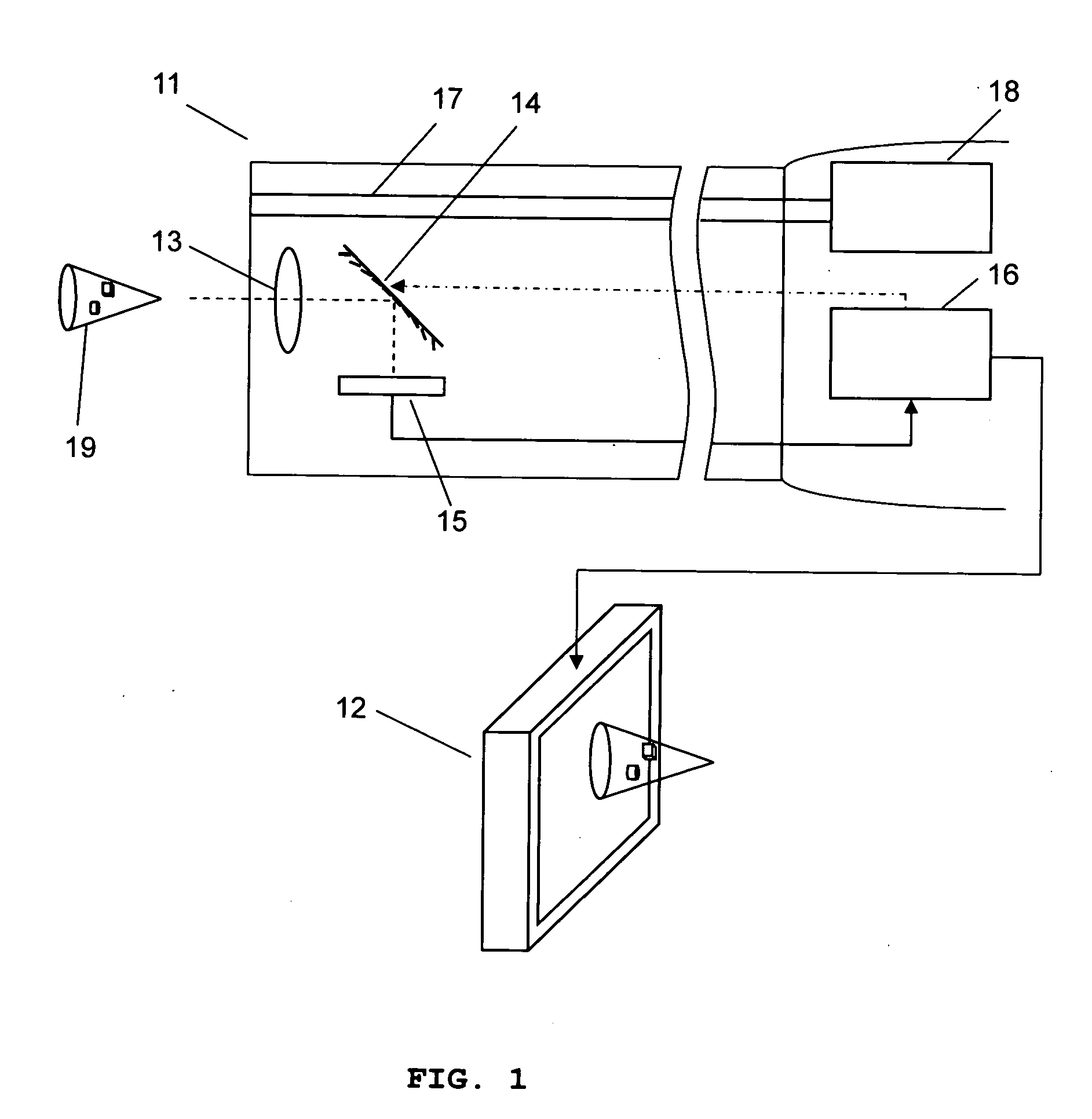
[0046]FIG. 1 schematically illustrates an endoscope system with a variable optical axis according to the one embodiment of the present invention. The endoscope device comprises an endoscope imaging device 11 and a three-dimensional display device 12. The endoscope imaging device 11 comprises a lens system 13, 14, an imaging unit 15, and an image processing unit 16. The lens system includes an objective lens 13, and a variable focal length MMAL 14, optically coupled to the objective lens 13, configured to change the focal plane by changing the focal length of the MMAL 14. The light delivery system 17 with a light source 18 illuminates an object of interest 19. The imaging unit 15 receives two-dimensional images of an object 19 with different focal planes that are shifted by changing the focal length of the variable focal length MMAL 14. The image depth of the focal plane is obtained from the focal length of the variable focal length MMAL. The image processing unit 16 extracts substan...


PUM


Abstract

The present invention provides a three-dimensional endoscope system comprising a three-dimensional imaging device and a three-dimensional display device using a variable focal length micromirror array lens. The micromirror array lens has enough focusing speed and focusing depth range for three-dimensional imaging and realistic three-dimensional display.

Description

REFERENCES TO RELATED APPLICATIONS [0001] This application is a continuation-in-part of, and claims priority to U.S. patent application Ser. No. 10 / 778,281 filed Feb. 13, 2004 (Docket No. 1802.01), U.S. patent application Ser. No. 10 / 822,414 filed Apr. 12, 2004 (Docket No. 1802.04), and U.S. patent application Ser. No. 10 / 979,624 filed Nov. 2, 2004 (Docket No. 1802.19), U.S. patent application Ser. No. 10 / 983,353 filed Nov. 8, 2004 (Docket No. 1802.013Con), U.S. patent application Ser. No. 10 / 872,241 filed Jun. 18, 2004 (Docket No. 1802.011), U.S. patent application Ser. No. 10 / 893,039 filed Jul. 16, 2004 (Docket No. 1802.012), all of which are hereby incorporated by reference.FIELD OF INVENTION [0002] The present invention relates to endoscope systems, and in particular, a three-dimensional endoscope system comprising a real-time three-dimensional imaging device and a three-dimensional display device. BACKGROUND OF INVENTION [0003] An endoscope is a minimal invasive imaging instrum...

Claims


Application Information

Patent Timeline
Patent Type & Authority Applications(United States)
IPC IPC(8): A61B1/04H04N13/395
CPCA61B6/466G02B26/0833G02B27/2278G03B21/28G03B35/18H04N13/0203H04N13/042H04N13/0495H04N13/395H04N13/204H04N13/322G02B30/52A61B1/00048
Inventor CHO, GYOUNG ILBAEK, SANG HYUNESEO, CHEONG SOO
Owner STEREO DISPLAY
Why Eureka
Try Eureka