Electrode for secondary battery, process of producing the electrode, and secondary battery

a secondary battery and electrode technology, applied in the field of electrode electrode for a secondary battery, can solve the problems of collector type electrodes, easy oxidation or corrosion of active materials, and difficulty in increasing energy density,

Inactive Publication Date: 2006-06-08
MITSUI MINING & SMELTING CO LTD
View PDF11 Cites 44 Cited by
  • Summary
  • Abstract
  • Description
  • Claims
  • Application Information

AI Technical Summary

Problems solved by technology

However, since the current collector used is as relatively thick as 10 to 100 μm, the proportion of the active material in the electrode is of necessity relatively small, which has made it difficult to increase the energy density.
Reducing the active material particle size to increase its specific surface area thereby to increase the output can invite another problem that such active material particles are susceptible to oxidation or corrosion.
Moreover, a collector type electrode tends to suffer from fall-off of the active material through expansion and contraction accompanying electrode reaction.
It has therefore been not easy to obtain an extended cycle life.
On the other hand, a foam type electrode is expected to have a high energy density but difficult to design to produce a high output.
A foam type electrode is as thick as about 1 mm, which is disadvantageous for making a flexible or compact electrode.
Besides, it is not easy to secure sufficient contact between the active material particles and the current collector.
However, the anode of Patent Document 4 undergoes noticeable deformation as a result of a failure to sufficiently accommodate volume changes due to expansion and contraction of the active material while charging and discharging.
When the active material cracks and crumbles through expansion and contraction, the anode is incapable of effectively preventing the active material from falling off.
Therefore, it is still difficult with this technique to provide an anode having improved cycle characteristics.

Method used


Image

  • Electrode for secondary battery, process of producing the electrode, and secondary battery
  • Electrode for secondary battery, process of producing the electrode, and secondary battery
  • Electrode for secondary battery, process of producing the electrode, and secondary battery

Examples


example 1

(1) Preparation of Active Material Particles

[0099] Raw materials of a hydrogen storage alloy were weighed out and mixed to give an alloy composition of MmNi4.45Mn0.45Al0.30Co0.10. The mixture was put into a crucible, and the crucible was set in a high frequency induction furnace, and the furnace was evacuated to 1.33×10⁻² Torr or lower. After the mixture was melted in an argon atmosphere, it was poured into a water-cooled copper mold and cast at 1430° C. to obtain an alloy. The alloy was heat treated at 1060° C. for 3 hours in an argon atmosphere to give a hydrogen storage alloy as an ingot. The ingot was ground and sieved into three fractions: 53 μm.

2) Preparation of Active Material Slurry

[0100] A slurry having the following composition was prepared using the 20-53 μm fraction of the hydrogen storage alloy.

Active material particles 50%

Acetylene black (particle size: 0.1 μm) 8%

Binder (styrene-butadiene rubber) 2%

Diluent (ethanol) 40%

3) Formation of Release Layer

[0101...

example 2

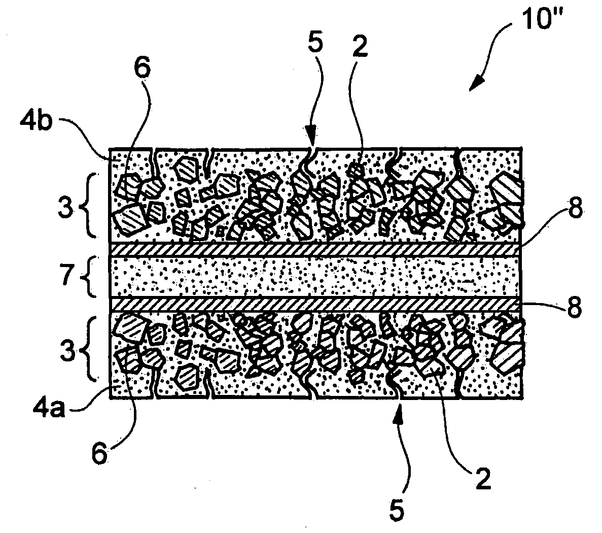
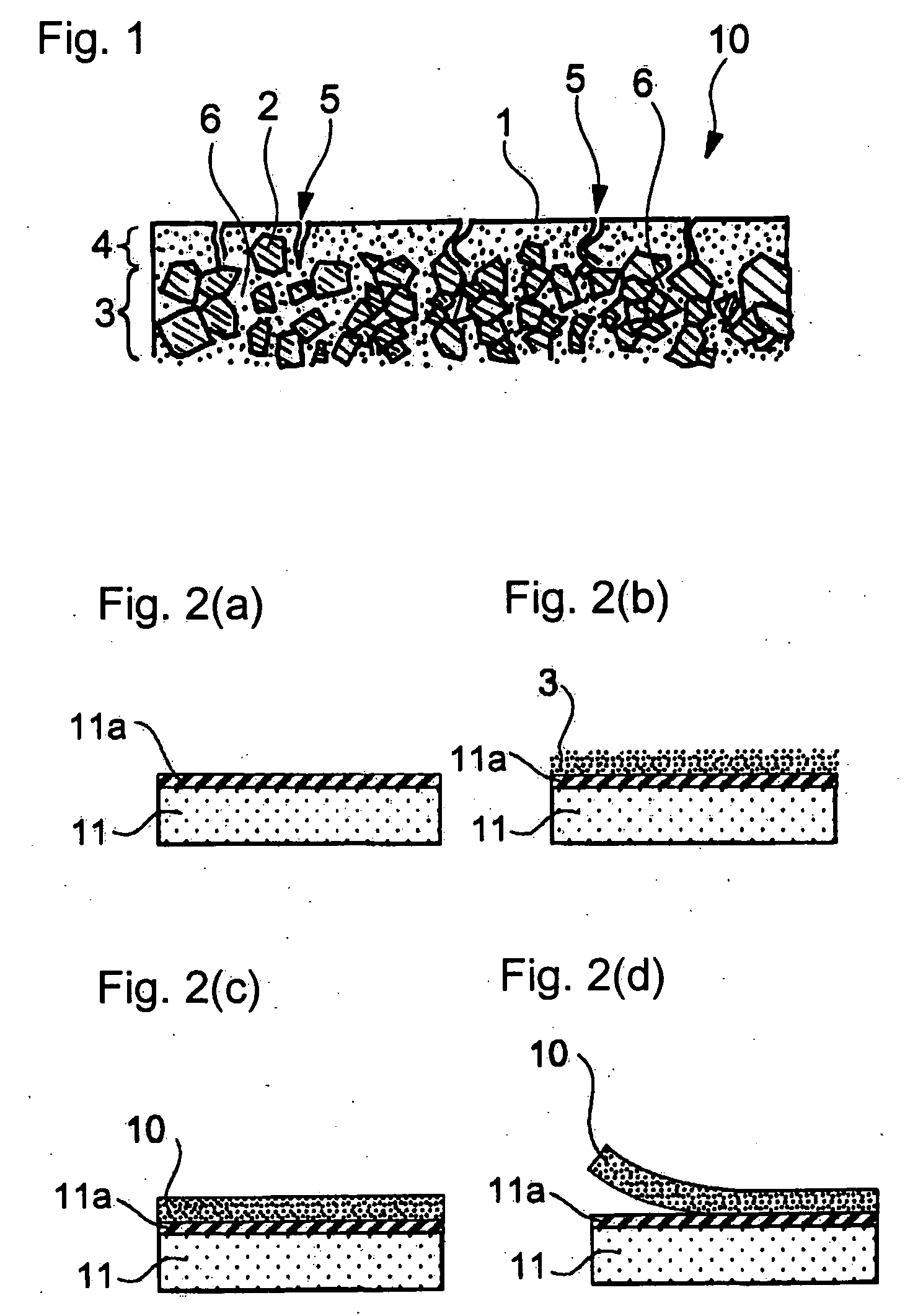
[0106] An anode having the structure shown in FIG. 1 was produced in the same manner as in Example 1, except for using the <20 μm fraction in place of the 20-53 μm fraction of the hydrogen storage alloy. An electron micrograph taken of a cut area of the resulting anode is shown in FIG. 8. An electron micrograph taken of the current-collecting surface layer of the anode that had faced the copper foil is shown in FIG. 9. While the micrograph of FIG. 8 does not clearly show the current-collecting surface layer that had faced the copper foil, FIG. 9 verifies the formation of the current-collecting surface layer with microvoids on the side that had faced the copper carrier foil. It was also confirmed that the active material layer was covered with the surface layer of that side and the active material particles were not exposed on the surface.

example 3

[0107] An anode having the structure shown in FIG. 1 was produced in the same manner as in Example 2, except for changing the plating time from 1180 seconds to 413 seconds. An electron micrograph taken of a cut area of the resulting anode is shown in FIG. 10. While not shown in the drawings, electron microscopic observation of the surface that had faced the copper carrier foil revealed the formation of the current-collecting surface layer with microvoids on that side. It was also confirmed that the active material layer was covered with that surface layer and the active material particles were not exposed on the surface.


PUM

PropertyMeasurementUnit
thicknessaaaaaaaaaa
total thicknessaaaaaaaaaa

Abstract

The invention provides an electrode as a cathode or an anode of a secondary battery. The electrode has a first and a second surface that are electrically conductive and adapted to be brought into contact with an electrolytic solution. The electrode has an active material layer containing active material particles between the first and second surfaces. The electrode has a large number of microvoids open on the first and second surfaces and leading to the active material layer.

Description

TECHNICAL FIELD [0001] This invention relates to an electrode for a secondary battery, more particularly to an electrode providing a battery having a high current collecting efficiency, a high output, and a high energy density and an electrode providing a secondary battery having an extended cycle life as a result of preventing the active material from falling off. The present invention also relates to a process of producing the electrode and a secondary battery having the electrode. BACKGROUND ART [0002] Electrodes that have been used in secondary batteries include those prepared by applying an active material paste containing particles of a hydrogen storage alloy, etc. to one or both sides of a current collector, such as a metal foil (hereinafter referred to as collector type electrodes). Also known are electrodes obtained by filling the pores of a metal foam with active material particles under pressure, followed by vacuum hot-pressing or sintering (see Patent Document 1) and tho...

Claims


Application Information

Patent Timeline
Patent Type & Authority Applications(United States)
IPC IPC(8): H01M4/02H01M4/58H01M4/04H01M4/13H01M4/139H01M10/052H01M10/36
CPCC25D1/04C25D15/00H01M4/0438H01M4/0452H01M4/13H01M4/139H01M4/242H01M4/385H01M10/052Y02E60/122Y02E60/124Y02E60/10
Inventor YASUDA, KIYOTAKAMUKAI, DAISUKEMATSUSHIMA, TOMOYOSHITAGUCHI, TAKEO
Owner MITSUI MINING & SMELTING CO LTD
Why Eureka
Try Eureka