
On demand boost conditioner (ODBC)

a technology of boosting conditioner and incoming air compressor, which is applied in the direction of combustion air/fuel air treatment, machines/engines, instruments, etc., can solve the problems of high heat soak, high cost, and high cost, and achieve the effect of low cos

Inactive Publication Date: 2006-06-08
PERKINS MICHAEL T
View PDF14 Cites 51 Cited by
  • Summary
  • Abstract
  • Description
  • Claims
  • Application Information

AI Technical Summary

Benefits of technology

"The present invention is an integrated system that works with a controller to manage air temperature, recharging, and emissions reduction in an engine. The system includes a smart controller that monitors engine and vehicle conditions and optimizes performance based on those conditions. The system also includes a chiller that increases air temperature, a warmer that preheats in cold conditions, a booster for faster engine response, and a buffer for increased power storage and operation duration. The system also includes advanced sensors to monitor engine performance and driver demands. The system can interface with host vehicle and vital operating information and is compatible with various computer bus standards. The technical effects of the invention include improved engine performance, reduced emissions, and optimized driving experience."

Problems solved by technology

These existing devices for improving power output on internal combustion engines suffer from various shortcomings that distract from their purpose, making power.
When turbo type technology is used exhaust backpressure is incurred, as is a high level of heat soak.
With these conditions the amount of power available is degraded substantially as is system reliability and longevity.
Therefore, reduced power gains are all that is available with these classical drive mechanisms.
These brackets, manifolds and plumbing are costly and take up space in already tight engine compartment.
Additionally, increases in power from larger boosting values result in considerable temperature increases of the air being inducted into a boosted engine.
Therefore, adding boost to engines increases the temperature inside the cylinders, at some point these additions of charged air will cause heat problems inside the combustion chamber.
Knock will result, causing an engine to fail very quickly and not produce expected or required amounts of power.
Boosted systems typically begin to experience these temperature problems in the 4 to 7 pounds per square inch (psi) boost range, depending on fuel, compression and valve timing.
The challenge confronting designers with these approaches centers on the high speed (measured in revolutions per minute (RPM)) with high torque requirements for the motor necessary to produce the desired performance.
These embodiments suffer from the same complications devices they are attempting to replace.
These complications include friction, gear lash, additional heat build up, and shortened life.
To date direct drive embodiments were not able to attain the power and speed necessary for performance that off sets the cost of system acquisition and operation.
Additionally, the attempts at solving reduced pressure at the reduced speeds have led to compromised supercharger designs in impeller size and shape.
These efforts have resulted in systems with shortened life spans and modest performance gains.
This deficit is due mostly to the lack of capabilities that follow.
No system capable of operating with a controller has been proposed that can provide data for supervisoral and scheduling operations, enhancements, recharging, and facility for system override of an actively chilled electronic supercharger.
No system can alternately cool or warm boosted air is available prior to FFC.
No electronically controllable booster that would integrate into an on-demand configuration with temperature compensation was available.
No system buffer was available that complements a smart controller.
No system that could provide advanced sensing capabilities for providing data for measurement of critical temperature and combustion signatures was available.
A reduction in air density reduces the amount of oxygen available for combustion and therefore reduces the engine horsepower and torque.

Method used


Image

  • On demand boost conditioner (ODBC)
  • On demand boost conditioner (ODBC)
  • On demand boost conditioner (ODBC)

Examples


Embodiment Construction

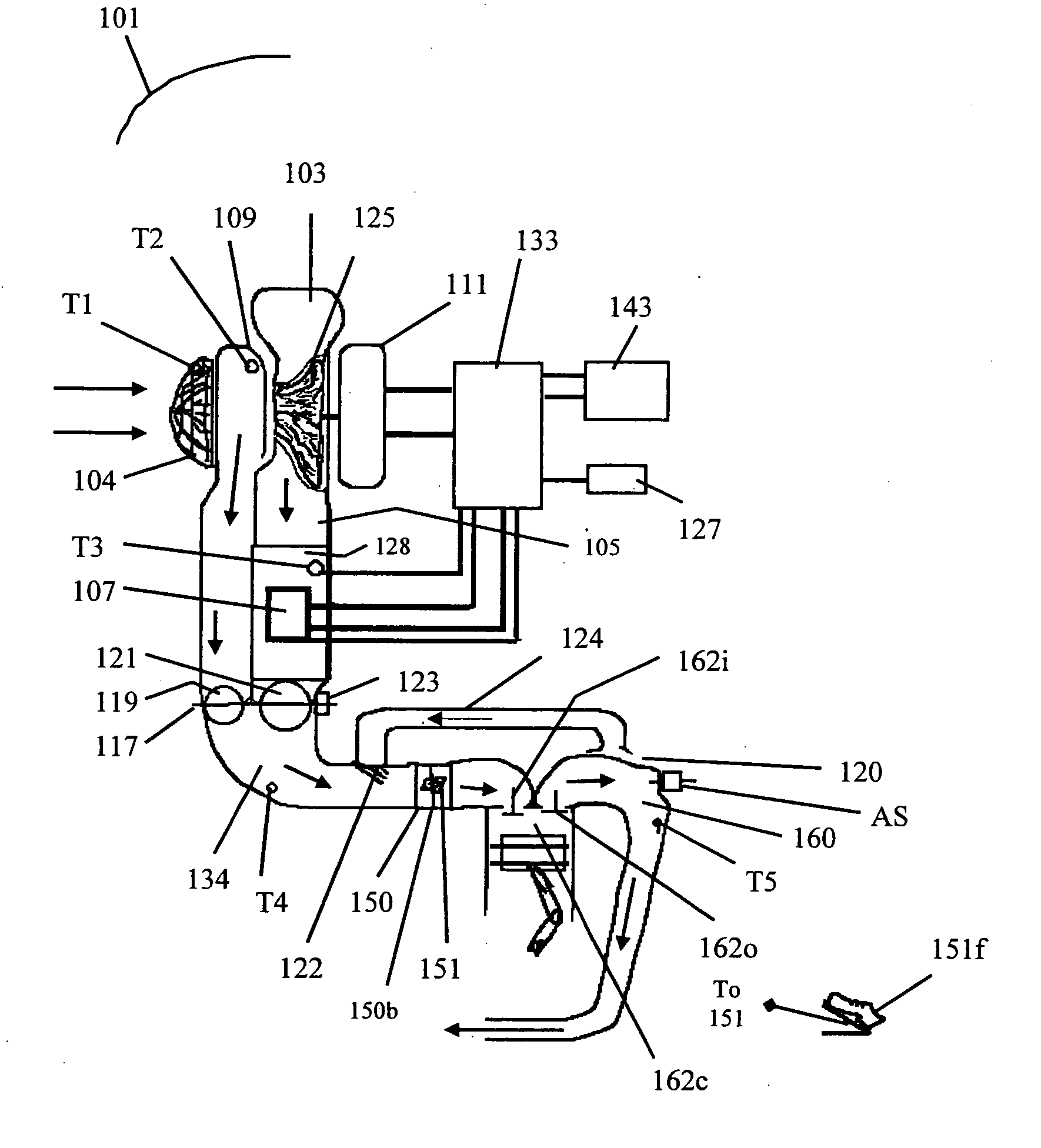
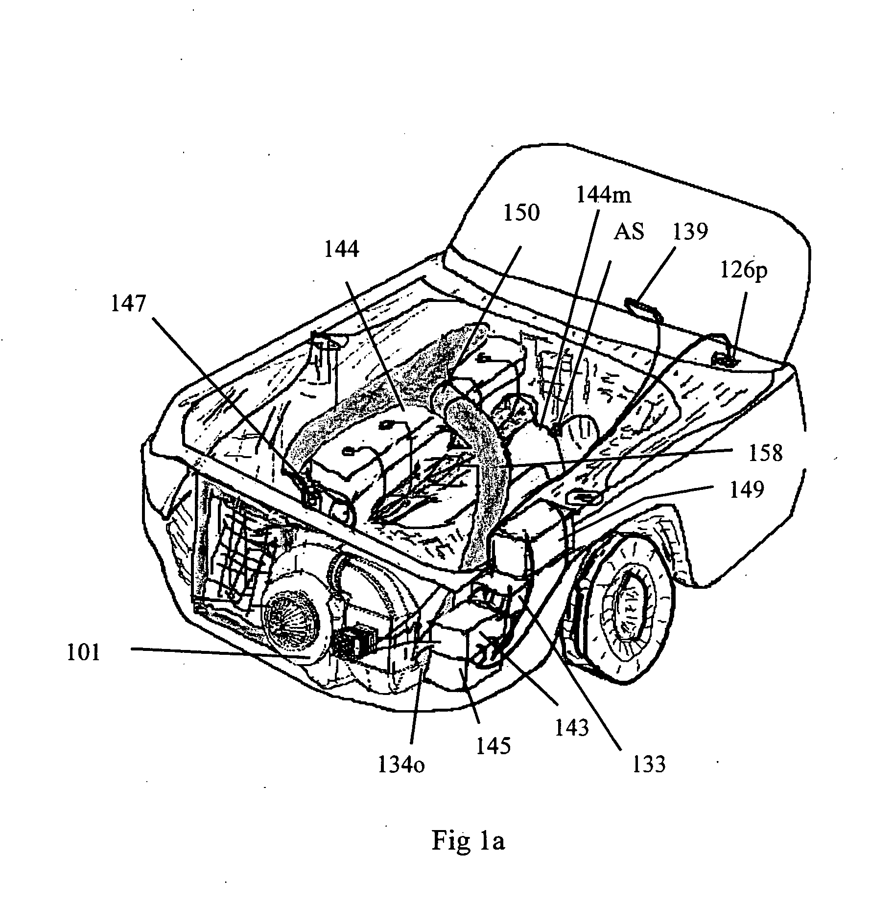
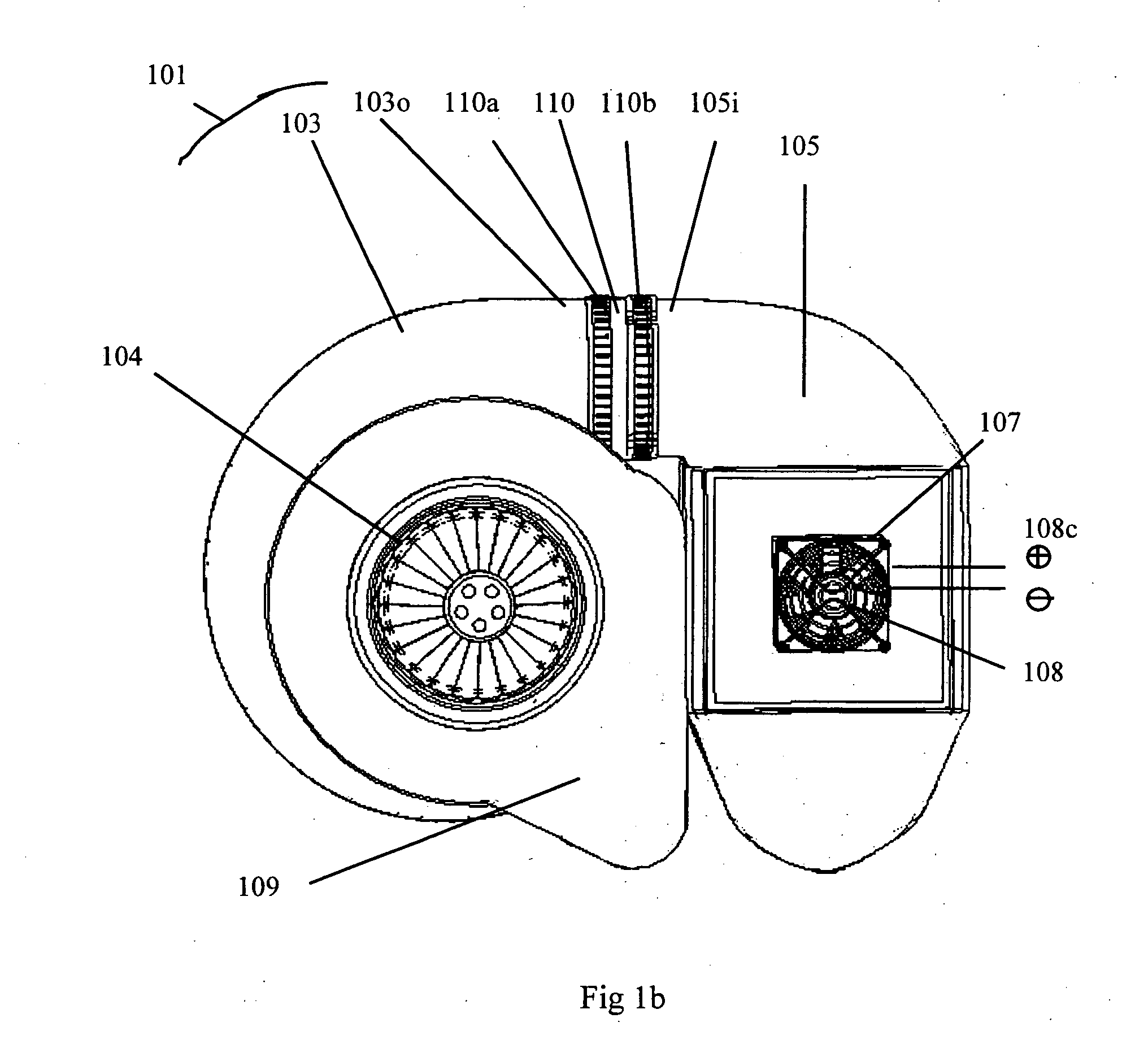
[0057]FIG. 1a is a perspective frontal view of the preferred embodiment of my invention, the On Demand Boost Conditioner (ODBC) 101 mounted in a host vehicle. The conditioner 101 is shown mounted next to the vehicle's radiator, in front of the vehicle firewall. This area of mounting conditioner 101 avoids heat soak disadvantages when compared to mounting conditioner 101 in an engine compartment behind firewall. Components of the system are shown in FIG. 2 for system perspective. Returning to FIG. 1a the conditioner 101 has an output 134o shown connected with an inlet hose 158 to a host vehicle engine 144 at a throttle body 150. The vehicle has an exhaust manifold 144m that is shown with an advanced sensor AS attached. Also shown are a vehicle battery 149, an alternator 147, an engine control unit (ECU) 126p connector, a display 139, a smart controller 133, a power buffer 143, and an auxiliary power 145. The system configuration is shown for discussion purposes as actual mounting in ...


PUM


Abstract

An integrated system for increasing power output from an internal combustion engine. System facilitates an interface for controlling and conditioning of the amount of intake air into an internal combustion engine. The system interfaces to a controller and provides critical data, an active intercooler, power buffer, and an electrically driven supercharger. An operator interface provides monitoring and control to a controller for expanded operator control. A power buffer relieves host power system from loading during high demand operation. A system of advanced sensors and processing from a controller combine to facilitate maximum power output with reduced risks. Active heat removal enables system operation in a vehicle at rest or in traffic. Active conditioning system flexibility facilitates improved implementation of cold temperature environment starting and operation. A low cost option with commercial non-positive displacement blowers implements affordable enhancements for internal combustion engines.

Description

FEDERALLY SPONSORED RESEARCH [0001] Not Applicable SEQUENCE LISTING OR PROGRAM [0002] Not Applicable BACKGROUND [0003] 1. Field of Invention [0004] The present invention relates to the field of electronically controlled incoming air compressors or boosters with active intercooling or after-cooling for enhancing power from such as internal combustion (compression or sparked combustion) engines (gas or other fuel). [0005] 2. Description of Prior Art [0006] The purpose of using compressors or boosters with internal combustion engines is to force a larger amount of air molecules into an engine (then the engine can ingest unaided). The motivation behind this purpose is to produce more power from the same engine. Classical configurations to facilitate boost on internal combustion engines have centered on exhaust driven (turbocharger) and belt driven (supercharger) technologies. These existing devices for improving power output on internal combustion engines suffer from various shortcoming...

Claims


Application Information

Patent Timeline
Patent Type & Authority Applications(United States)
IPC IPC(8): G06F19/00F02B33/00F02B29/04
CPCF02B29/0481F02B29/0493F02B33/40F02B33/443F02B39/10F02M31/083F02M31/13Y02T10/146Y02T10/126Y02T10/12
Inventor PERKINS, MICHAEL T.
Owner PERKINS MICHAEL T
Learn More